Do you have a question about the Haier GE AZ45E07DABW5 and is the answer not in the manual?
General safety warnings and experience requirements for servicing. Emphasizes personal injury and property damage risks.
Lists required safety gear, including safety glasses, gloves, and steel toe shoes for all repairs.
Details the 6-step process required before disassembling the Zoneline to ensure safe servicing.
Lists essential tools needed for maintenance and repair of the Zoneline unit.
Compares typical system pressures for R-22 and R-410A systems for technician reference.
Explains the meaning of each character and digit in the Zoneline model number.
Details how the first two characters of the serial number indicate the month and year of manufacture.
Describes compressor, fan, and reversing valve operation in cooling mode for AZ4500 and AZ6500.
Details the operation of the resistance heater in heating mode for the AZ4500 model.
Explains the three stages of heating operation for heat pump models (AZ6500).
Covers Heat Pump Lockout, Boost Heat, and Fan Only modes for enhanced control.
Describes the fan's cycling behavior during the cooling mode operation.
Details the fan's cycling during resistance heating mode.
Explains the fan's cycling pattern when operating in heat pump mode.
Allows continuous fan operation, providing air circulation even when the unit is off.
Explains how the unit restarts after a power outage to prevent inrush current.
Describes the mechanism to prevent the indoor coil from freezing during cooling.
Details the protection system against indoor coil overheating in heat pump mode.
Outlines the conditions, sequence, and faults for the reverse cycle defrost.
Describes the ICR system's function to evaporate condensate water during heat pump operation.
Explains Heat Sentinel, Freeze Sentinel, and Control Lockout functions for unit management.
Guide on using the Auxiliary Set button to configure various operational settings and modes.
Details on connecting Central Desk Control (CDC), remote thermostats, and external fans.
Provides tables of resistance values for indoor and outdoor thermistors at various temperatures.
Identifies key components and connectors on the front cover of the main control board.
Details available power cords, their amperage ratings, and features like LCDI protection.
Locates major components such as the compressor, relays, and transformer on the main board.
Lists specific resistance checks for main board components like fan motors, pumps, and heaters.
Lists and explains various fault codes, their effects on operation, and reset times.
Instructions for entering and using diagnostic service modes for AZ4500 and AZ6500 models.
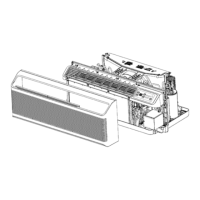
Describes how to access the control area, capacitor, and other connections.
Procedure for diagnosing the low voltage transformer by checking AC volts on a connector.
Explains how to configure personality settings on the service main board for model compatibility.
Describes the indoor fan motor, its assembly, and the indoor blower wheel.
Instructions for accessing and replacing the indoor fan bearing assembly.
Details the outdoor fan shroud's function and how it attaches to the unit.
Describes the outdoor fan motor, its securing bolts, and a note on wire clip repair.
Explains the three-bank heater assembly and its protective thermal switches.
Provides steps for disconnecting the wire harness and removing the heater assembly.
Describes the ICR system for pumping and evaporating condensate water.
Explains how the fan blade's slinger ring aids in condensate dissipation.
Introduces the damper door and Make-Up Air Module for fresh air intake.
Details MUAM operation, fault detection, and relevant fault codes for troubleshooting.
Lists basic components of the sealed system including coils, compressor, and metering device.
Details compressor wiring checks, resistance, and the function of the reversing valve.
Emphasizes the necessity of replacing the drier during sealed system repairs and check valve function.
Illustrates the path of refrigerant through the system during cooling operation.
Illustrates the path of refrigerant through the system during heat pump operation.
Provides instructions and diagrams for the safe recovery of refrigerant.
Lists refrigerant charge amounts for various models and hook-up diagrams.
Presents the overall wiring diagram and a key for wire colors used in the unit.
Lists various optional accessories, their part numbers, and descriptions.
| Brand | Haier |
|---|---|
| Model | GE AZ45E07DABW5 |
| Category | Air Conditioner |
| Language | English |