7
8. MAINTENANCE
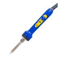
● Tip maintenance
Please refer to the FM-202 Instruction manual.
● Checking Procedure
WARNING:
Unless otherwise directed, carry out these procedures with the power switch OFF and the power
UNPLUGGED.
■ Verify the electrical integrity
of the heater and sensor
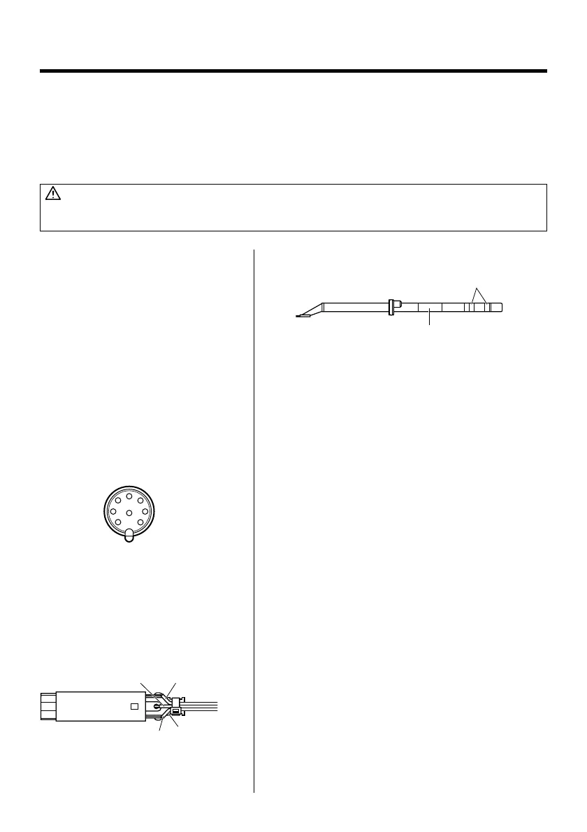
1. Check for a broken heater or sensor
Measure the resistance across the tip as shown.
Measure the resistance while at room
temperature(15 to 25°C; 59 to 77°F). It should
be 8Ω±10%. If the resistance exceeds these
limits, replace the tip.
Measure the resistance across this position
Tip ID
■ Check the grounding line 1. Unplug the connection cord from the station.
2. Measure the resistance value between pin 2
and the tip (both tips).
3. If the value exceeds 2Ω (at room tem-
perature), perform the tip maintenance
described on P.12 of the FM-202 instruction
manual. If the value still does not decrease,
check the connection cord for breakage.
■ Checking the connection
cord for breakage (Refer to
P.11 WIRING DIAGRAM of B
side.)
1. Remove the soldering tip and the handle.
2. Measure the resistance values between the
connector and the lead wires at the socket
as follows:
Pin 1 – Red Pin 2 – Green
Pin 3 – Black Pin 5 – White
If any value exceeds 0Ω or is ∞, replace the
FM-2022.
1
4
7
2
8
5
6
3
Green
B side socket
Black
Red
White (inside)