Installation and Commissioning
15.11.2018
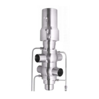
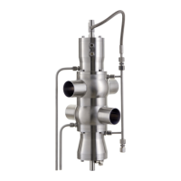
DOUBLE-SEAT VALVE INOVA (Type 580)
BA 058000.06 EN 23 / 36
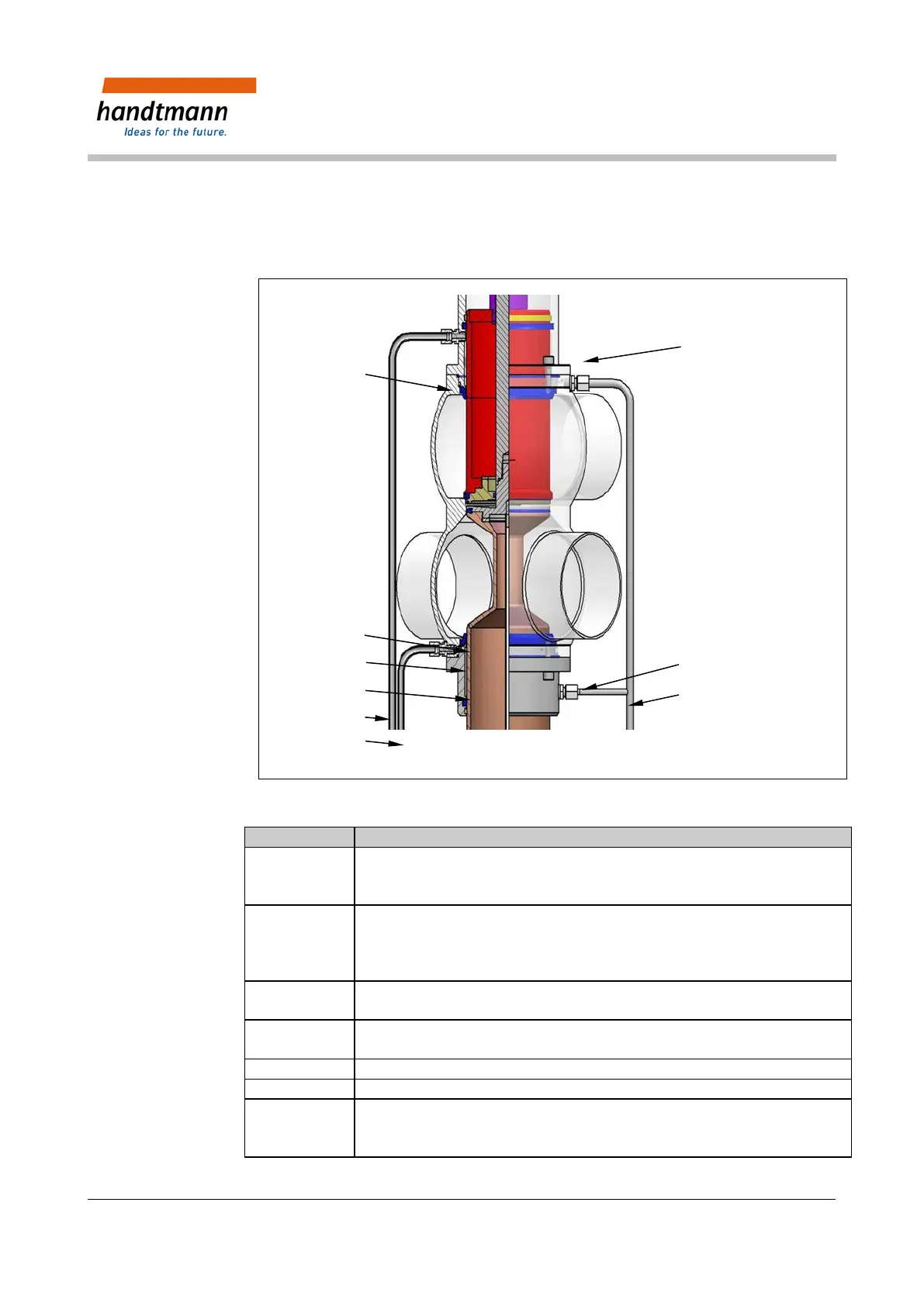
7.2 Installation of the Valve inset
Please note the following instructions for assembling the valve inset so that the later
functionality of the valve is ensured.
12
Fig. 9: Representation of the valve inset
1 Install the lower bushing [2] with seals [6, 7] and screw together with the
valve housing [3 below].
Position the bushing after the connection nipple for CIP collecting pipe [45].
2 Locate the complete valve inset tension-free in the valve housing [1]. In this
state, the leakage chamber is closed.
Position the valve inset after connection for CIP collecting pipe [45]. Turn
only in a clockwise direction.
3 Screw [3] the valve inset complete with the valve housing [1]. In the process
the lower balancer is pushed down and the leakage chamber is opened.
Tighten the collecting pipe [45] and the overflow pipe [43, 44]; if necessary
screw on the external CIP supply pipe.
Attach the electrical connections to the control unit (Chapter 4.1.2).
Carry out a seal and function check.
Direct or indirect control through compressed air (Chapter 6.4)
Three compressed air connections G1/8" for direct activating of the three
drive functions; main stroke (A), upper lifting (B), lower lifting (C).
2
6
7
3
1
43