16
INSTALLATION
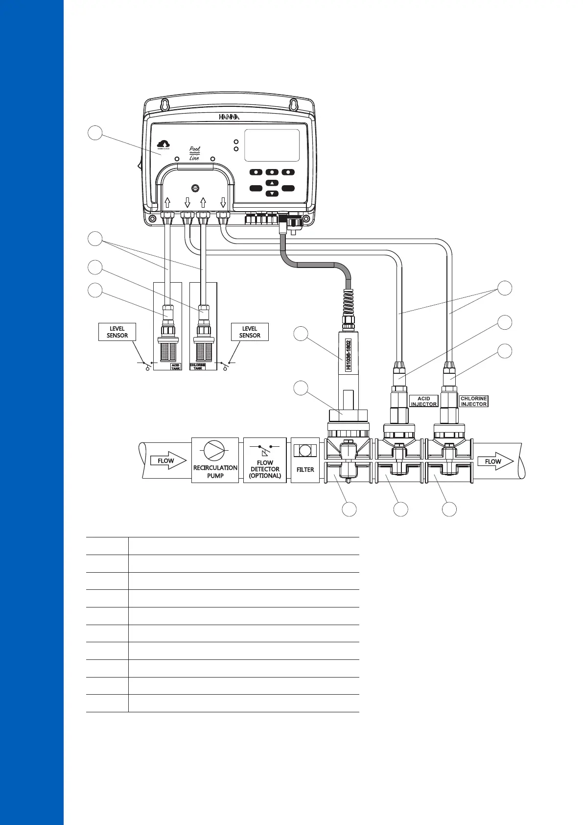
In-Line Installation Overview & Components Table
Below is an illustrated reference of a generic, in-line installation scheme with the relevant components.
HELP
MENU
ChlorinepH
SWIMMING POOL CONTROLLER
SERVICE
STATUS
BL123
7
7
5
1
6
6
4
2
3
8 9 9
Position Component description
1 Pool controller
2 pH/ORP/temperature electrode
3 Electrode fitting
4 Flexible tubing for pump input
5 Rigid tubing for pump output
6 Aspiration filter
7 Injector, ½” thread
8 Probe saddle for Ø 50 mm pipe, using1 ¼” thread
9 Injector saddle for pipe, using 1/2” thread
Note: Connections for flow detector and for level sensor (acid & chlorine tanks) are optional.
 Loading...


