Do you have a question about the Hanna Instruments EC Series and is the answer not in the manual?
Critical precautions for electrical connections, installation, and maintenance to ensure personnel safety.
Overview of EC/TDS controllers, intended applications, and key functionalities.
Details the physical size and shape of the probe, including length and connection type.
Illustrates the color-coded connections for the probe to the controller terminals.
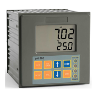
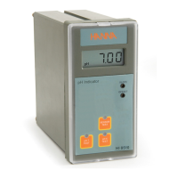
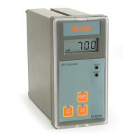
Describes the LCD, buttons, and LED indicators on the front of the controller.
Details the terminals for probe, power supply, and external controls on the rear of the unit.
Explains the process of mounting the controller into a panel, including cutout dimensions.
Provides specific instructions for connecting the probe and power supply to the rear terminals.
Covers overtime control, external disabling contact, and 4-20 mA output.
Step-by-step guide for calibrating the EC/TDS controller using standard solutions.
Explains how to set the threshold value for triggering control actions.
Details cleaning and storage recommendations to maximize probe lifespan.
Lists ordering codes and descriptions for probes, solutions, and adapters.
Provides user recommendations, compliance information, and warranty terms.
The Hanna Instruments EC and TDS Process Mini Controller Series are compact, panel-mount units designed for convenient measurement of electrolytic conductivity in process streams. These controllers are intended for industrial applications, utilizing relays and outputs to interact with valves or pumps for process monitoring and control.
The controllers are equipped with a clear LCD that displays measurement values in units such as ppmppt, mSµS, µS/cm, mS/cm, mg/L (ppm), or g/L (ppt), depending on the specific model. An LED operational indicator provides visual feedback on the instrument's status: green for measurement mode, orange-yellow for active dosing, and red (blinking) for an alarm condition.
The front panel features a dosing switch with three positions: OFF (dosing disabled), AUTO (automatic dosing based on a setpoint value), and ON (dosing enabled). A MEAS key allows the user to switch to measurement mode, while a SET key is used to configure the display value. Both SET and CAL trimmers are available for adjusting the setpoint value and for calibration, respectively.
On the rear panel, the probe connection terminal facilitates low voltage connections, with color-coded terminals for easy wiring. Power supply terminals accommodate either 12 VDC for BL9833XX-0 models or 115/230 VAC for BL9833XX-1 and BL9833XX-2 models. A relay contact acts as a switch to drive the dosing system.
An overtime feature is included for system control, allowing users to set a maximum continuous time for the relay to run a pump or valve, adjustable via a trimmer from approximately 5 to 30 minutes. If the set time expires before the setpoint is reached, dosing stops, the LED indicator blinks red, and a "TIMEOUT" message is displayed. This feature can be disabled by removing a jumper from the rear panel.
For BL9833XX-2 models, an external disable input is available, which, when closed, stops dosing, causes the LED indicator to blink red, and displays a "HALT" warning message. These models also include 4-20 mA galvanic isolated output contacts for connecting to process control signal outputs.
The controllers offer flexible dosing modes, with an option to select either manual or automatic operation. In automatic mode, the dry contact dosing relay activates when the reading is above or below a programmable setpoint, depending on the model. The programmable overdosing timer prevents continuous dosing if the setpoint is not reached within a specified time interval, enhancing safety and efficiency.
Temperature compensated readings are provided from 5 to 50 °C (41 to 122 °F), ensuring accuracy across a range of operating conditions. Internal fuse-protected dosing contacts offer an additional layer of safety. The large, clear LCD and LED indicator make it easy to monitor the instrument's status, and a splash-resistant transparent cover protects the unit in various environments.
Calibration is a straightforward process. Users immerse the probe in a calibration solution, allow the reading to stabilize, and then adjust the CAL trimmer until the LCD displays the nominal value of the solution. This ensures accurate measurements for the specific application.
Setpoint configuration involves pressing the SET key, which displays the current setpoint value. A small screwdriver is then used to adjust the SET trimmer to the desired setpoint. The instrument automatically resumes measurement mode after one minute, or the MEAS key can be pressed to return immediately. The setpoint incorporates a typical hysteresis value to prevent rapid switching.
For monitoring, users immerse or install the probe in the solution to be monitored and press the MEAS key. The LCD will display the measured value, and the LED indicator will show whether the instrument is in measurement mode (green) or if dosing is in progress (orange/yellow).
Regular cleaning and correct storage are crucial for maximizing the probe's lifespan. The recommended cleaning procedure involves immersing the tip of the probe in HI7061 Cleaning Solution for one hour. For more stubborn deposits, the metal pins can be gently brushed with very fine sandpaper. After cleaning, the probe should be rinsed with tap water and recalibrated to ensure continued accuracy. Finally, the probe should be stored clean and dry.
The instrument is designed for easy installation, with mounting brackets provided. The rear panel connections are clearly labeled, and low voltage connections for the probe are color-coded to simplify wiring. Power supply connections are also clearly indicated for both 12 VDC and 115/230 VAC models.
The controllers are built to conform to CE European Directives and are RoHS compliant, indicating adherence to environmental and safety standards. Users are advised to ensure the instrument is suitable for their specific application and environment to maintain performance and safety. All external cables connected to the rear panel should be fitted with cable lugs, and a clearly marked disconnect switch (max. 6A) must be installed nearby to de-energize the electrical circuit for service or maintenance.
| EC Resolution | 0.01 μS/cm, 0.1 μS/cm, 1 μS/cm, 0.01 mS/cm, 0.1 mS/cm |
|---|---|
| EC Accuracy | ±1% of reading |
| Temperature Resolution | 0.1°C / 0.1°F |
| Temperature Accuracy | ±0.5°C (±1°F) |
| Output | 4-20 mA |
| Environment | 0 to 50°C (32 to 122°F), RH max 95% non-condensing |


 Loading...