Functional Description 6
6. FUNCTIONAL DESCRIPTION
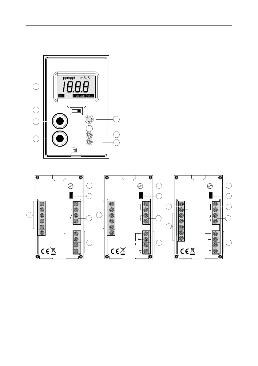
6.1. FRONT PANEL
Black
Stone
AUTO
OFF
ON
MEAS
SET
CAL
SET
1
2
3
4
6
7
5
1. LCD
2. Dosing switch
• OFF (dosing disabled)
• AUTO (automatic dosing, setpoint value)
• ON (dosing enabled)
3. MEAS key (measurement mode)
4. SET key (configure display value)
5. SET trimmer (adjust setpoint value)
6. CAL trimmer
7. LED operational indicator
• Green – measurement mode
• Orange‑Yellow – active dosing
• Red (blinking) – alarm condition
6.2. REAR PANEL
Dosing
contact
min
max
Time
NU
GND
NU
12VDC
White or
Brown
Grey
Green
Yellow
NU
Shield
NU
BL9833XX-0
1
5
4
3
2
Dosing
contact
min
max
Time
50/60Hz; 10 VA
115 V
230 V
PE
White or
Brown
Grey
Green
Yellow
NU
Shield
NU
BL9833XX-1
1
5
4
3
2
Dosing
contact
min
max
Time
BL9833XX-2
White or
Brown
Grey
Green
Yellow
Shield
4-20 mA
Output
50/60Hz; 10 VA
115 V
230 V
PE
External
Disabling
1
5
4
6
3
2
7
BL9833XX-0 BL9833XX-1 BL9833XX-2
1. Probe connection terminal, low voltage connections
2. Power supply terminal
• BL9833XX‑1 & BL9833XX‑2, line voltage connections, 115/230 VAC
• BL9833XX‑0, low voltage connections, 12 VDC
3. Relay contact acts as a switch for driving the dosing system
4. Jumper for enabling (jumper inserted) or disabling (jumper removed) the overtime control
5. Trimmer for overtime setting (approx. from 5 to 30 minutes)
6. External control for dosing system disabling (BL9833XX‑2)
7. 4‑20 mA output contacts (BL9833XX‑2)

 Loading...