7 Installation
7. INSTALLATION
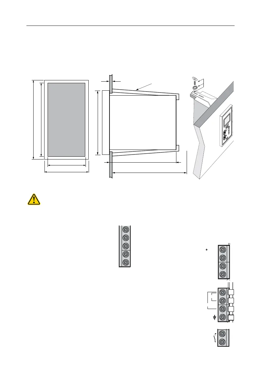
7.1. UNIT MOUNT
Front view
outside panel cutout
Side view
mounting bracket & inside depth
Top view
mounting bracket
43 mm (1.7”)
74 mm (2.9”)
53 mm (2.0”)
(0.01/0.16”)
Adjustable
Location Bracket
81 mm (3.2”)
95 mm (3.7”) MIN
Bracket
WARNINGS
All external cables connected to the rear panel should be fitted with cable lugs.
A clearly marked disconnect switch (max. 6A) must be installed in the vicinity of the instrument to
ensure that the electrical circuit is completely de‑energized for service or maintenance.
7.2. REAR PANEL CONNECTIONS
Probe terminal
• Follow color code to connect the probe.
Power supply terminal
• BL9833XX‑0
Connect the 2 wires of a 12 VDC power adapter to the +12 VDC and GND terminals.
• BL9833XX‑1 & BL9833XX‑2
Connect a 3‑wire power cable paying attention to the correct contacts:
• earth (PE)
• line (L), 115 VAC or 230 VAC
• neutral (N1 for 115 V or N2 for 230 V)
Dosing Contact
• Dosing contact (NO) output drives the dosing system as per configured setpoint.
White or
Brown
Grey
Green
Yellow
Shield
4-20 mA
Output
50/60Hz; 10 VA
115 V
230 V
PE
Dosing
contact
min
max
Time
White or
Brown
Grey
Green
Yellow
Shield
4-20 mA
Output
50/60Hz; 10 VA
115 V
230 V
PE
N1
N2
PE
L
NU
GND
NU
12VDC
White or
Brown
Grey
Green
Yellow
NU
Shield
Dosing
contact

 Loading...