18
INSTALLATION
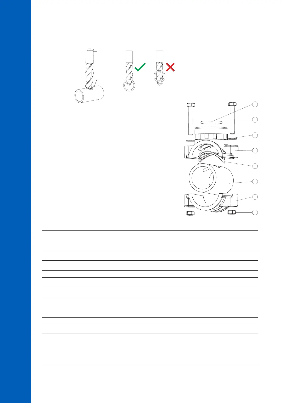
6.3. MOUNTING RECOMMENDATIONS FOR SADDLE
• Select required drill size. See table below for dimension details.
Drill
Pipe
• Place the upper part of the saddle (5) on top of the pipe (3) with the
seal (4) placed over the hole.
• Take the lower part of the saddle (2), together with inserted nuts (1)
and align it under the upper part.
• Insert the screws (7) with washers (6) through the holes and hand
tighten into the mounted nuts.
• With all the screws (7) in place, use a wrench to carefully tighten.
• Place the O-ring (8) provided into the upper saddle.
Probe Saddle (In-line Configuration) Thread Size Drill Size
BL120-550 Ø 50 mm pipe 1 ¼”thread 29 mm - 32 mm / 1.14” - 1.26”
BL120-563 Ø 63 mm pipe 1 ¼”thread 29 mm - 32 mm / 1.14” - 1.26”
BL120-575 Ø 75 mm pipe 1 ¼”thread 29 mm - 32 mm / 1.14” - 1.26”
Valve Fittings (Flow Cell Configuration) Thread Size Drill Size
BL120-450 Ø 50 mm pipe ½”thread 20 mm - 25.4 mm / 0.79” - 1.00”
BL120-463 Ø 63 mm pipe ½”thread 20 mm - 25.4 mm / 0.79” - 1.00”
BL120-475 Ø 75 mm pipe ½”thread 20 mm - 25.4 mm / 0.79” - 1.00”
Injector Saddle Thread Size Drill Size
BL120-250 Ø 50 mm pipe ½”thread 20 mm - 25.4 mm / 0.79” - 1.00”
BL120-263 Ø 63 mm pipe ½”thread 20 mm - 25.4 mm / 0.79” - 1.00”
BL120-275 Ø 75 mm pipe ½”thread 20 mm - 25.4 mm / 0.79” - 1.00”
6
4
1
5
2
3
7
 Loading...


