22
An upper boundary is imposed for dosage time when relays
are energized continuously, i.e. when relay works in ON/
OFF mode or also in PID mode but in the latter case only if
the relay is always ON. This parameter can be set through
the setup procedure. When the maximum boundary is
reached, an alarm is generated; the device stays in alarm
condition until relay is de-energized.
ON/OFF CONTROL MODE
Either for mode 1 or 2 (high or low
conductivity dosage) the user has to
define the following values through
setup:
• relay setpoint (µS/mS/ppm value);
• relay hysteresis (µS/mS/ppm value).
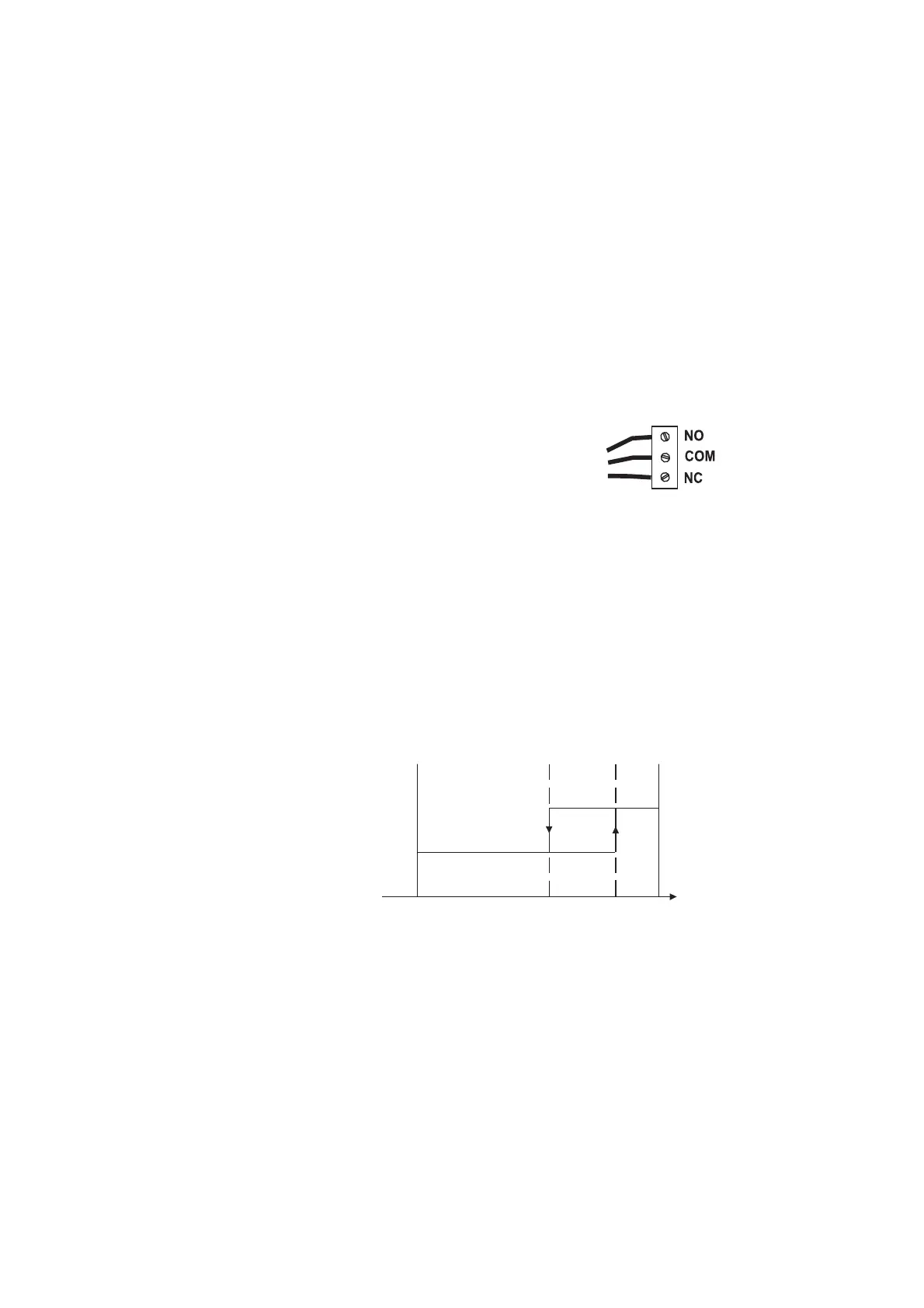
Connect your device to the COM and NO (Normally Open)
or NC (Normally Closed) terminals.
The ON relay state occurs when relay is energized (NO and
COM connected, NC and COM disconnected).
The OFF relay state occurs when relay is de-energized (NO
and COM disconnected, NC and COM connected).
The following graphs show relay states along with EC mea-
sured value (similar graph can be derived for TDS control).
As shown below, a high setpoint relay is activated when the
measured EC exceeds the setpoint and is deactivated when it
is below the setpoint value minus hysteresis.
Such a behavior is suitable to control a high conductivity
dosing pump.
A low setpoint relay as can be seen from the following graphs
is energized when the EC value is below the setpoint and is
ON
OFF
Setpoint
EC
Setpoint –
Hysteresis

 Loading...


