14
Connect the two signal wires from the transmitter to terminals
#5 on page 8, paying attention to the correct polarity. Termi-
nal 14 is the positive input and terminal 15 is the negative
input.
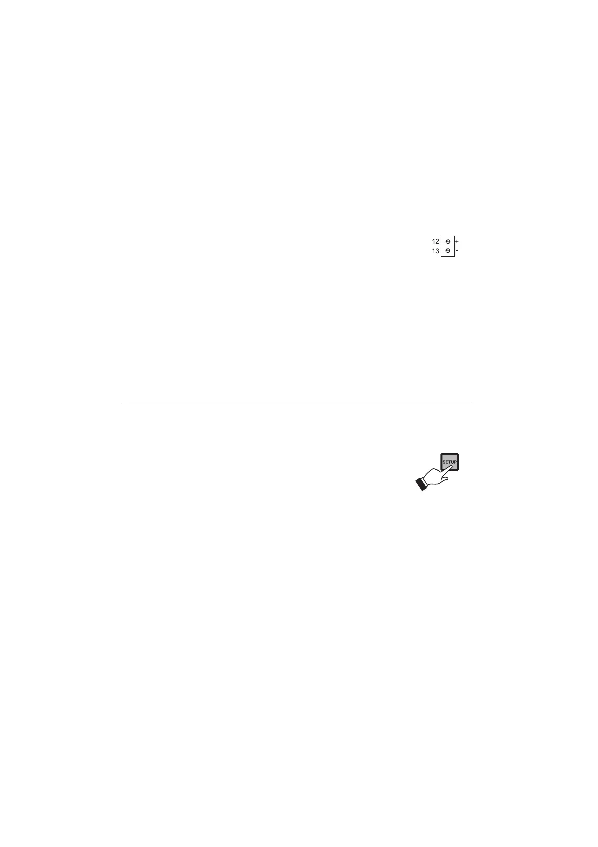
An unregulated 10 ÷ 30 VDC - 50 mA max.
power supply output (#4 on page 8) is pro-
vided to power the transmitter, if needed. Pin
12 is the positive voltage terminal and pin 13
is the negative voltage terminal.
Once the installation is completed, select the appropriate
working range, the reference temperature (20 or 25°C) and
perform conductivity or TDS calibration as described in this
instruction manual. Set the control parameters according
to the process of interest.
SETUP MODE
The Setup Mode allows the user to set all needed character-
istics of the meter.
The setup mode is entered by pressing SETUP
and entering the password when the device
is in idle or control mode.
Generally speaking, if the password is not inserted the user
can only view the setup parameters (except for password)
without modifying them (and the device remains in control
mode). An exception is certain setup items, or flags, which
can activate special tasks when set and confirmed.
To each setup parameter (or setup item) is assigned a two-
digit setup code which is entered and displayed on the
secondary LCD.

 Loading...


