1818
-18-
6.7. GREASE LUBRICATION POINTS (see fig. 5, pages 16 - 17)
All greasing points for bearings which are not oil lubricated and for labyrinth seals are equipped
with nipples according to DIN 71412 and have been filled before shipment.
The total number of nipples is indicated on the nameplate.
Some built-on backstops are grease lubricated.
For detailed information refer to appropriate leaflet supplied with this manual.
6.8. OIL DRAINING
Drain the oil while unit is still warm. To facilitate oil draining, remove dipstick. Drain
units having a large oil volume through drain plug. Use portable pump. With some executions a
small quantity of oil remains beneath the high speed bearings. This oil can be drained by means
of a second drain plug (1)(see fig. 5, page 16).
6.9. VENTILATION (see fig. 5, page 16).
To prevent pressure build-up, the gear unit is provided with a breather which is generally
integrated in the dipstick.
Take care and check regularly that this breather does not become clogged.
For some applications, the dipstick with breather hole is replaced by one without breather hole
in combination with an anti-dust or anti-humidity breather.
7. COOLING
Heat generated in the gear unit due to friction and churning of the oil, must be dissipated
through the housing into the environment.
It is important not to decrease the heath dissipation capacity of the housing.
Regularly clean the surface of the housing.
7.1. SEPARATE AIR COOLING
7.1.1. Fans
One or two fans may be mounted on gear unit shafts.
Check regularly that the air inlet and the air outlet are not obstructed.
Fans need no special maintenance, except occasional cleaning.
7.1.2. Air-oil coolers
The service manual of the lubrication and cooling system gives detailed information about the
air-oil cooler.
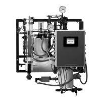
7.2. SEPARATE WATER COOLING
All water cooling systems must be connected to a non-calcareous water supply. See also
service manual on lubrication and cooling system and/or technical leaflets on specific
instrumentation. The use of seawater must be specified with the order; coolers suited for use of
seawater are available.
When unit is not operating and freezing temperatures may occur, water must be drained from
cooling system. Drain facilities have to be provided by end user.
Unless otherwise stipulated, the water flow indicated on the dimensional drawing is the required
rate for water at 20°C (70°F).
According to load, ambient temperature and the water temperature a lower rate will suffice.
Adjust waterflow to obtain an oil working temperature between 60 and 80°C (140 and 180°F).