Basic Operation
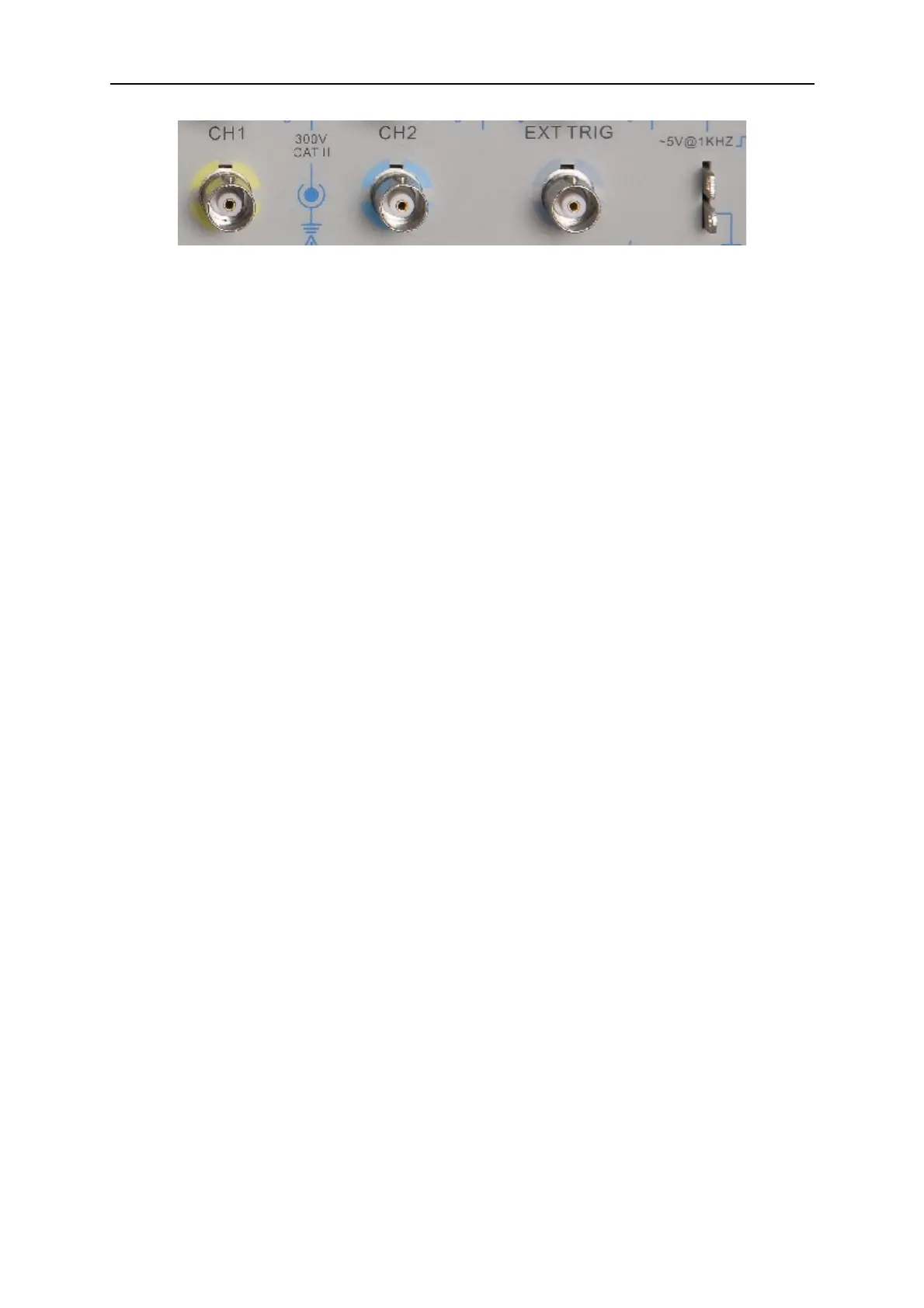
1. CH1, CH2: Input connectors for waveform display, through which to connect and input the
signal to be measured.
2. EXT TRIG: Input connector for an external trigger source, though with to connect and input
the external trigger signal.
3. Probe Compensation: Voltage probe compensation output and ground, used to electrically
match the probe to the oscilloscope input circuit. The probe compensation ground and BNC
shields connect to earth ground and are considered to be ground terminals. To avoid
damages, do not connect a voltage source to any of these ground terminals.
DSO5000 Series Digital Storage Oscilloscope User Manual 49
 Loading...