Basic Operation
DSO5000P Series Digital Storage Oscilloscope User Manual 43
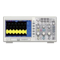
5.8 Signal Connectors
See the figure below to find the three signals connectors and a pair of metal electrodes at the
bottom of the oscilloscope panel.
1. CH1, CH2: Input connectors for waveform display, through which to connect and input the
signal to be measured.
2. EXT TRIG: Input connector for an external trigger source, though with to connect and input the
external trigger signal.
3. Probe Compensation: Voltage probe compensation output and ground, used to electrically
match the probe to the oscilloscope input circuit. The probe compensation ground and BNC
shields connect to earth ground and are considered to be ground terminals. To avoid damages,
do not connect a voltage source to any of these ground terminals.
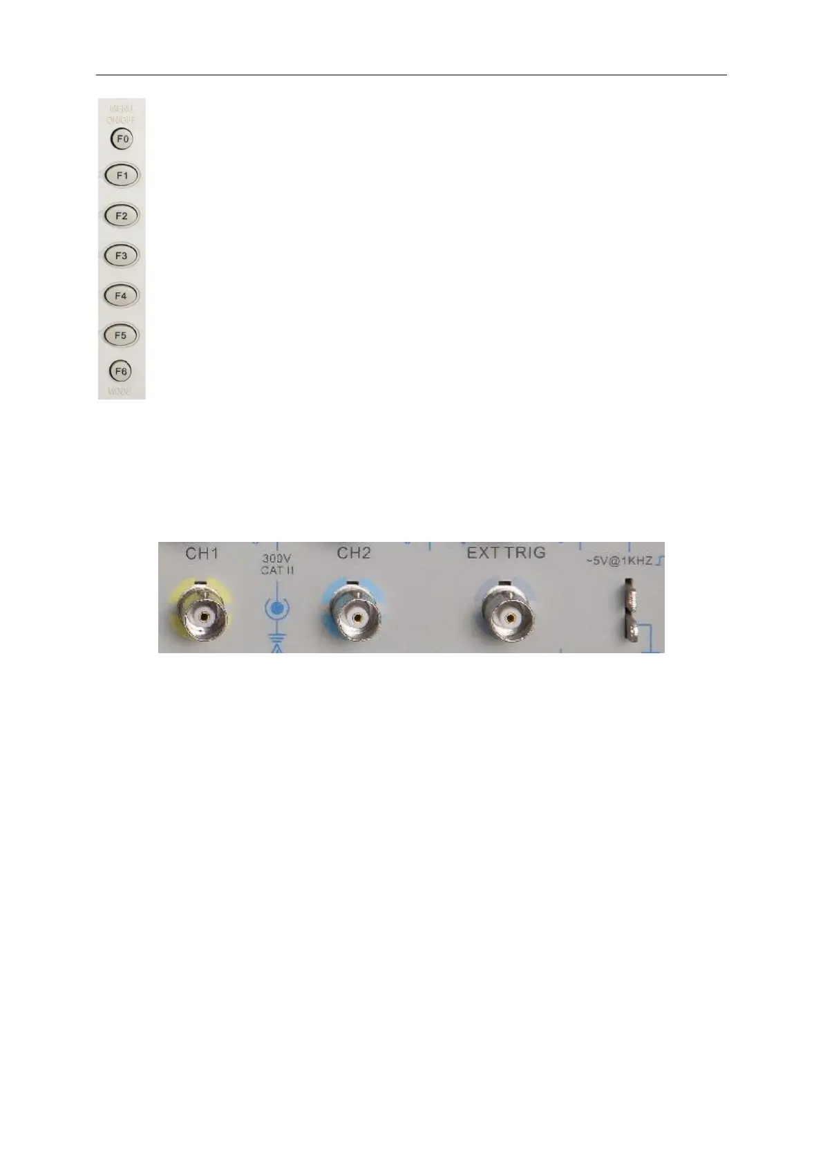
F0: Hide/Show button. Push it to hide the menu options on the right side of the
screen and give a full screen display of waveforms. Push it again to show the menu
options.
F1-F5: These five buttons are all multi-functional. They are in charge of selecting
corresponding menu options on the screen in different menu modes. For example, in
the UTILITY menu, F1-F5 respectively correspond to ‘System Info’ – ‘Advance’.
F6: This functional button is mainly used to turn pages and confirm a selection, such
as ‘next page’, ‘previous page’, and ‘press F6 to confirm’ appearing when you push
Self Calibration option.