Do you have a question about the Hantek DSO2C10 and is the answer not in the manual?
Check shipping container, accessories, and instrument for damage after receiving.
Adjust supporting legs for stable placement and connect the power cord.
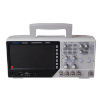
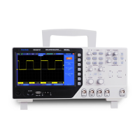
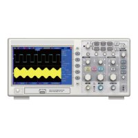
Overview of the oscilloscope's front panel controls, ports, and indicators.
Explanation of the oscilloscope's on-screen display, including status and channel info.
Perform a quick functional check by connecting the probe and observing the waveform.
Guidance on safe probe usage, manual compensation, and attenuation settings.
Description of front panel buttons for navigation, operation modes, and system functions.
Details of input/output connectors like CH1, CH2, and EXT TRIG/GEN OUT.
Explanation of the multifunctional knob and softkey operations for menu interaction.
Features for Auto Scale, saving/recalling setups, and default configuration.
Controls for adjusting the horizontal position and time base (SEC/DIV).
Controls for vertical position, VOLTS/DIV, and channel-specific settings.
Performing arithmetic operations (add, subtract, multiply, divide, FFT) on waveforms.
Concepts of trigger sources, modes, position, level, and holdoff.
Triggering based on the rising or falling edge of a signal.
Triggering on pulses with specific width conditions (less than, greater than, etc.).
Capturing and triggering on standard video signals like NTSC and PAL.
Triggering based on the time taken for a signal to transition between levels.
Triggering when a signal stays above or below a level for a specified time.
Triggering when a signal crosses specific high and low level thresholds.
Triggering based on a specified logical pattern of signal states across channels.
Triggering based on the time difference between signal edges.
Triggering on pulses that cross one threshold but not another.
Triggering on UART serial data based on start, stop, parity, or data.
Triggering on LIN bus signals based on frame ID, sync, or error conditions.
Triggering on CAN bus signals based on frame type, ID, or error conditions.
Triggering on SPI bus signals based on data and timeout conditions.
Triggering on IIC bus signals based on start, stop, address, or data.
Enabling and configuring protocol decoding for serial communication.
Interpreting and displaying decoded UART data on the waveform.
Interpreting and displaying decoded LIN data on the waveform.
Interpreting and displaying decoded CAN data on the waveform.
Interpreting and displaying decoded SPI data on the waveform.
Interpreting and displaying decoded IIC data on the waveform.
Saving and recalling oscilloscope setups, waveforms, and reference data.
Methods for saving and recalling data to/from the oscilloscope's internal memory.
Procedures for saving/recalling data to/from USB storage devices.
Saving screenshots of the oscilloscope display to a USB storage device.
Managing files and folders on external USB storage devices.
Overview of the oscilloscope's measurement capabilities.
Performing quick measurements using graticule divisions and scale factors.
Using on-screen cursors for precise time and voltage measurements.
Automated measurement of waveform parameters like frequency, amplitude, etc.
Using the oscilloscope as a Digital Voltmeter for voltage and frequency.
Settings and modes for capturing waveform data.
Controlling waveform acquisition: Run, Stop, and Single shot capture.
Displaying waveforms with CH1 on the horizontal axis and CH2 on the vertical axis.
Displaying waveforms by scrolling from right to left, useful for slow signals.
Adjusting waveform display style, intensity, grid, and brightness.
System settings including language, sound, update, pass/fail, and info.
Procedure for updating the oscilloscope's software via USB.
Running the self-calibration routine for optimal measurement accuracy.
Configuring pass/fail testing based on signal criteria and outputting results.
Using buttons like Auto Set, Default Setup, Save To USB, and Decode for quick operations.
Automatically adjusting settings to display input signals clearly.
Restoring the oscilloscope to its factory default configuration.
Displaying waveforms in two separate windows for detailed analysis.
Selecting and configuring waveform types, frequency, amplitude, and duty cycle.
Applying amplitude or frequency modulation to generated waveforms.
Configuring the waveform generator for burst output with a specified number of cycles.
Creating and editing custom waveforms using the WaveEditor software.
Downloading custom waveforms to the oscilloscope or recalling them from USB.
Connecting the oscilloscope to a PC for remote operation and data transfer via USB.
Solutions for startup failures, no waveform display, and distorted signals.
Details on how to contact HANTEK distributors, field offices, and headquarters.
Guidelines for protecting the device from sunlight, liquids, and solvents.
Instructions for cleaning the oscilloscope exterior and probes using lint-free cloths.
Technical details for horizontal measurement accuracy and ranges.
Technical details for vertical measurement accuracy, range, and bandwidth.
Specifications for sample rate, acquisition modes, and memory depth.
Detailed parameters for various trigger types (Edge, Pulse, UART, etc.).
Specifications for input channels, probes, and signal isolation.
Specifications for cursor, automatic, DVM, and math measurements.
Specifications for saving/recalling data internally and to external memory.
Specifications for waveform generation, modulation, and burst modes.
Specifications for display type, resolution, brightness, and grid.
Specifications for standard interfaces (USB) and power supply requirements.
Operating temperature, storage temperature, humidity, and altitude limits.
List of standard accessories included with the oscilloscope.
Table detailing the presence of harmful substances in oscilloscope components.
| Bandwidth | 100 MHz |
|---|---|
| Channels | 2 |
| Sample Rate | 1 GSa/s |
| Memory Depth | 8 Mpts |
| Trigger Types | Edge, Pulse, Video, Slope, Alternative |
| Display Resolution | 800 x 480 pixels |
| FFT | Yes |
| Math Functions | +, -, *, /, FFT |
| Power Supply | 100-240 V AC, 50/60 Hz |
| Display | 7 inch LCD |
| Vertical Resolution | 8-bit |
| Interface | USB host, USB device |
| Input Impedance | 1 MΩ ± 2% |
| Waveform Capture Rate | 50, 000 wfm/s |