Multi Loop Controller
6
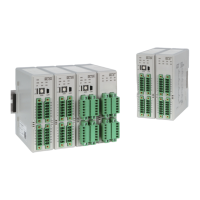
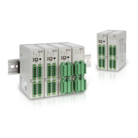
2.2 Connection diagram
2.2.1 Name of each part
①
②
⑦
⑧
⑨
⑥
⑤
④
③
No. Name Function
① Status indication LED
Power supply, communication, event, control
output, heater break event indication
② Loader Jack
RS232C communication input terminal
③ Unit address switch
RS485 communication address setting switch
(0~15)
④
Unit extension
address switch
RS485 communication extension address setting
switch (0 /+16)
⑤
CH 1 terminal
Temperature input and current transformer (CT)
input terminal
⑥
OUT 1: heating control output terminal
OUT 2: cooling control output terminal
⑦
CH 2 terminal
Temperature input and current transformer (CT)
input terminal
⑧
OUT 1: heating control output terminal
OUT 2: cooling control output terminal
⑨
Power source and
communications
termina
RS485 communications and 24 V d.c. input
terminal
※ If unit extension address switch is positioned at “+16” and unit address
switch is positioned at “1,” RS485 communications address is set to “1+16=17.”
█ ML-D2H
①
②
⑦
⑧
⑨
⑥
⑤
④
③
No. Name Function
① Status indication LED
Power supply, communication, event,
control output indication
② Loader Jack RS232C communication input terminal
③ Unit address switch
RS485 communication address setting switch
(0~15)
④
Unit extension
address switch
RS485 communication extension address
setting switch (0 /+16)
⑤ CH 1 terminal
Input signal (sensor)
Temperature input and control output terminal
⑥
CH 2 terminal
⑦ CH 3 terminal
⑧ CH 4 terminal
⑨
Power supply and
communications
terminal
RS485 communications and
24 V d.c. input terminal
※ If unit extension address switch is positioned at “+16” and unit address
switch is positioned at “1,” RS485 communications address is set to “1+16=17.”
█ ML-D4
 Loading...