Page 18 <&(%$*4.8"4,7%H'*#$"&8#I%/7*,#*%4,77%JKLLLKLMMKNOPO1 Item 56825
?@<6AQ D@CEA6E@ER6S@?CR%T6GUCEV T6GUCEV%ACW?SETUP
?$"4Y%T*79"83
AX%W;6!6EA%?6;CXF?%CE`F;Q%@EU%U6@AB-%%%
U&%8&$%)*79%)"$.&'$%V(&'89"83%R7,5/1%%
T.*8%$.*%&/*(,$&(%"#%8&$%.&79"83%$.*%67*4$(&9*%B&79*(I%"$%5'#$%+*%
#"$$"83%&8%,%8&84&89'4$"Z*I%8&827,55,+7*%#'(2,4*1%%
1. Turn the Power Switch to the OFF position, then
plug the Welder into a properly grounded, GFCI
SURWHFWHG9$&DPSUDWHGRXWOHWRU
9$&UHFHSWDFOHWKDWPDWFKHVWKHSOXJ
The circuit must be equipped with delayed
action-type circuit breaker or fuses.
2. Set Electrode Holder down on
nonconductive, nonflammable surface
away from any grounded objects.
3. Turn the Power Switch ON.
T@;ECEVc%%AX%W;6!6EA%?6;CXF?%CE`F;Q- T.*8%
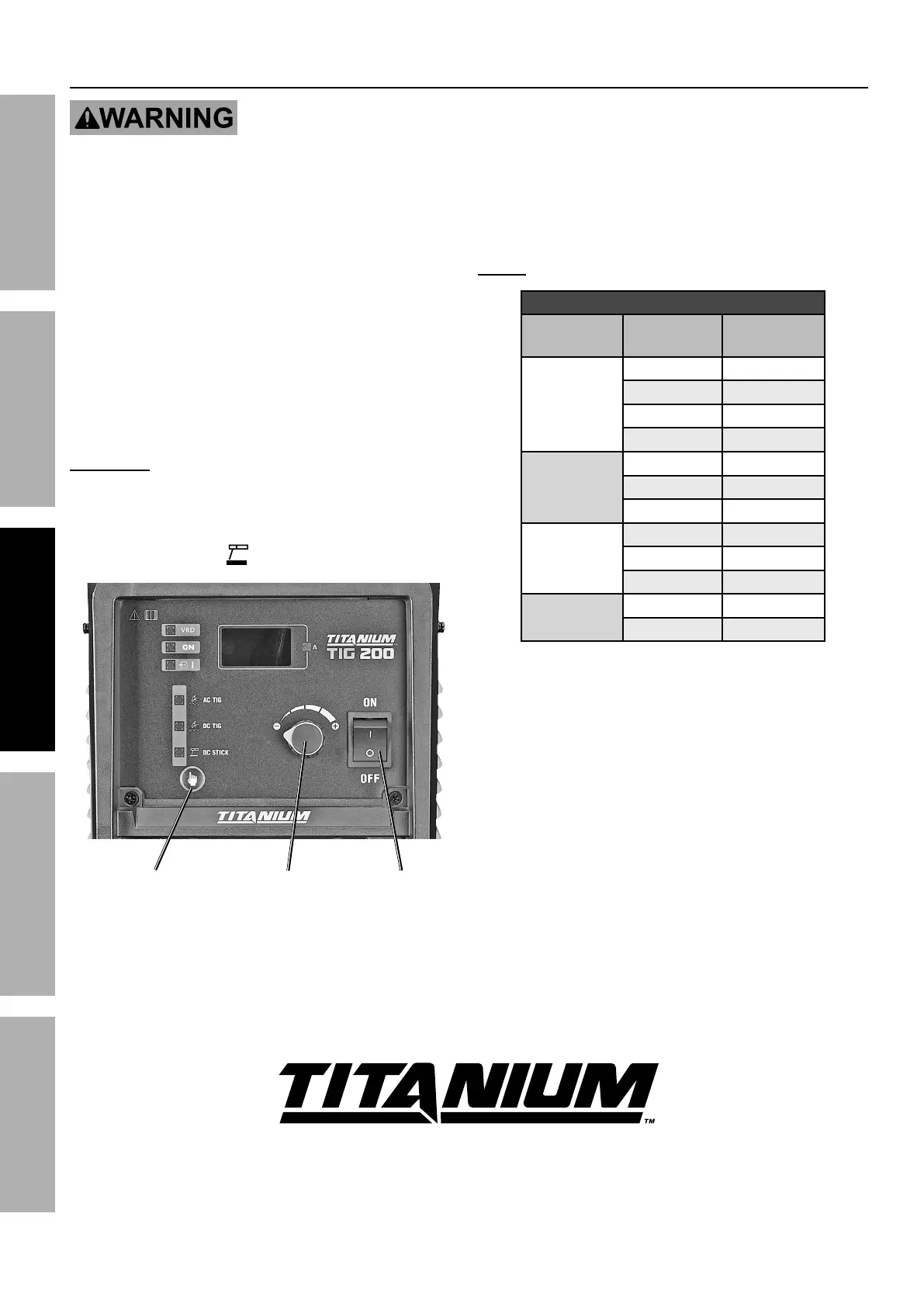
?$"4Y%"#%#*7*4$*9I%T*79*(%"#%*8*(3"\*9I%B&$%?$,($%"#%
,4$"Z,$*9%,89%X/*8%R"(4'"$%!&7$,3*%"#%/(*#*8$1
4. ?*7*4$%W(&4*##- Press Welding Mode
Switch to scroll to %%UR%?ACR[.
R'((*8$%
X'$/'$%[8&+
T*79"83%
D&9*%?)"$4.
W&)*(%
?)"$4.
5. Set Amperage according to Stick Settings Chart.
EXA6- Settings are approximate. Adjust as necessary.
?$"4Y%?*$$"83#%R.,($%
67*4$(&9*%
A>/*
67*4$(&9*%
U",5*$*(
@5/*(,3*%
;,83*
6M^Ja%URg
J0JMh
a0abh N^KP^
J0Lh P^KJa^
N0abh Ja^KJON
('&
a0abh O^KJJ^
J0Lh P^KJa^
N0abh Ja^KJON
6O^JL%URg
a0abh ONKJJ^
J0Lh P^KJaN
N0abh Ja^KJON
('&
J0Lh Jb^KJN^
N0abh JM^KJON