20 HARDI
®
NAVIGATOR 550M, 800M, 1000M CENTRIFUGAL OPERATOR'S MANUAL
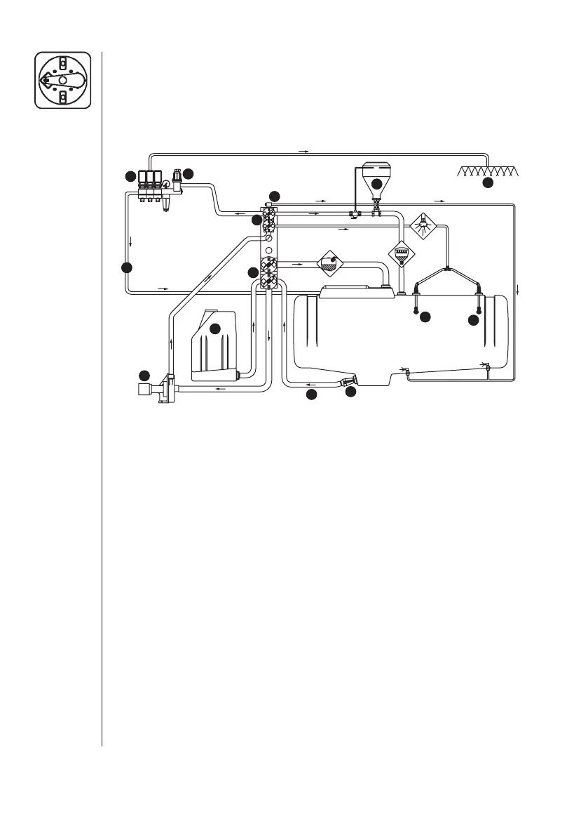
4.4 Manifold Sprayer Plumbing Diagram
Review and study the following diagram. By fol low ing the fl ow through
the diagram, you will better un derstand the various functions of your
spray er system.
ESC (with optional equipment)
The di agram shows the Standard plumbing with examples of op tions
avail able.
Function Diagram
1. Suction line 8. Distribution valves
2. Suction manifold (black) 9. Spray boom
3. Pump 10. Pressure equalization return
4. Pressure man ifold (green) 11. Flush tank*
5. Pressure Agitation 12. HARDI
®
chemical inductor*
6. On/Off valve 13. Tank rinse nozzles*
7. Pressure adjustment
*optional equipment
4.5 Manifold Sys tem
The “Manifold Sys tem” is lo cated at the left hand side of the sprayer,
per mitting op er ation of most of the (fi t ted) ac cessories from one po sition.
The modular design of the Man ifold sys tem allows the easy addition of
many ac cessories to the plumb ing sys tem of the spray er. The system
can be ex panded to a maximum of 4 valves on the pres sure side and 2
valves on the suction side.
9
8
7
11
13
6
4
2
3
10
12
1
5
13
 Loading...