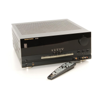
CONNECTING THE 730
E3efow
procc,ecJ111Q
wrth
the
connection
ul
tric,
730
there
1s
one
other
1tern
that you
sliould
take
care
of
Since
you Ii ave
1ust
purchased
the unit you
should
still
have
tlie
bill of sale.
Make
sure
111s
clc,arly
markccJ
show111g
the
cJate
of
purchase
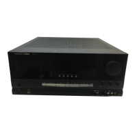
Now
look
on the
mar
panel
of the 730
and
1ocate the serial
nwntJcr
Record
this
rwmtJcr
or1
the
tJ1II
of sale
and
tlien
put
rt
away
111
a
safE,
place
for future refere11ce
T111s
number
wrll
be
1mporta11t
11
your
u111t
requires
warranty
service
It
may
also
prov-ca
useful
1cJc11t1f1cat1or11f
your urnt
becomes
sub1ect
to
theft
On
tlie
rear par1el
ol
trie
730
yo,, will
f111cJ
m1mero11s
receptacles.
a:I
clearly
ancJ
specifically
marked
w1t11
1de11tify111g
legends.
Each
ol tl1ese will
tJe
dealt
w1t11
111
t11rn
For
the
moment.
leave
the
power
cord
of
tl1e
730 unconnected.
Place
tl1e
730
on
a
shelf
or table. or
or1
t11e
tloor
near
wliere
1t
will finally
be
placed
wtien
you ve
completed
tile
connections.
You
st1oulcJ
leave
enougl1
working
space
armmcJ
1t
so
you
can
make
your
corinect1or1s
easily
and
comfortably
Although
tile
730
1s
a
solid
state
device.
its
powerful
amplifiers
arid
even
dial
scale
illum1nat1on
lamps
will
generate
l1eat. The 730
1s
designed
to
operate
eff1c1ently
over
a
wide
range
of
ambient
temperatures.
but
the l1eat
1t
generates
must
be
allowed
to
escape
to
prevent
internal
temperatures
from
r1s1ng
too
l11gh.
Adequate
vent1lat1or1
must
be
provided.
If
the
730
will
operate
on an
open
shelf,
no
special
precaut1or1s
11eed
be
taken.
If
a
shelf will exist atJove
tlie
730.
allow
at
least
1"
to
2" of free
space
above
the
receiver.
If
the
730
will
operate
1n
a 3
or
5-sided
(bottom,
back.
top
and
sides)
closed
space.
at
least
2" to 4" of free
space
sliould
be
allowed
above
1t
and
to
e1tl1er
side.
In
custom-mounted
cabinet
installations.
adequate
air flow
can
be
obtained
by
dr1ll1ng
a
large
cutout,
or.
several
small
lioles.
1n
tlie
surrounding
cabinetry.
both
above
and
below
the
receiver
(not
1n
the 730
housing
I
11)
Open
back
custom
installations
require
no
special
attention. Finally. free air flow
t11rougl1
the
bottom
of
tlie
receiver
must
be
allowed
Never operate the 730 on a rug
or cushion that could prevent air from
entering the bottom of the receiver.
SPEAKER
SYSTEMS
Preparing for Connections:
Cl1oos1ng
tlie
r1gl1t
wire for
connecting
your
speakers
to the
receiver
will
assure
the
best
performance.
We
recommend
use
of 18
gauge.
strancJed.
two-conductor
wire. This
type
of
wire
1s
often
called
lamp,
or zip.·
cord
and
1s
available
at
most
high
fidelity
stores
or
any
electrical
supply
store Wire of 18
gauge
1s
thick
enough
to
allow
lengtlis
of
up
to
50
feet to
tJe
used
w1t11out
affecting
tl1e
low
frequency
performance
of
your
system.
For
longer
runs.
we
suggest
thicker
16
gauge
wire
If
t11e
lengtl1 of wire you
need
1s
relatively
short. you
may
use
t111nner
20
gauge
wire
for
your
1nstallat1on. althougl1 18
gauge
wire
1s
preferred
Lamp
cord
11s11ally
provides
a·
code'
wl11ch
1s
a
means
ol
1dent1fy1ng
tlie
conductors.
On
some
brancJs
tr1e
1nsulat1on
surrounding
one
of
tlie
conductors
lias
a rib.
sliarp
corner
(see
•a").
or
1ndentat1ons
molded
along
its
lengt11
(see
"b
')
on
otliers
a
t111n
colored
t11read
1s
molded
1ns1de
tl1e
insulator
along
w1tl1
one
conductor
(see c ') In still
otlier
tJrands.
tlie
two
coriductors
are
different
colors
(see·
d")
S11cl1
wire will
be
very
useful
1n
"pl1as1ng·
your
s1Jeaker
systems
Ci1t
two
lengtlis
of
wire
ol
approximately
eq11al
size.
Bot11
sl1ould
be
long
enougl1 to
comiortably
reac
1
1
tne
s(ieaker
t11at
will
tJe
at
t11e
greatest
distance
from
tlie
730
Separate
tlie
conductors
at eacl1
end
of
tiie
wire
segments
a
distance
ol
about
2-3".
t11en
carefully
remove
about
one-l1alf
1nct1
of
1nsulat1on
from
eacl1 free
end
Twist
me
strands
of eacl1 cond11ctor so tr1ey are
smoot11
and
tight
without
any
loose
strands
 Loading...