30 OPERATION
Operation
Output Level Trim Adjustment
Normal output level adjustment for the
AVR 3500 is established using the test tone, as
outlined on pages 22 and 23. In some cases,
however, it may be desirable to adjust the output
levels using program material such as a test disc,
or a selection you are familiar with. Additionally,
the output level for the subwoofer and those for
the Stereo and VMAx modes can only be adjust-
ed using this procedure.
To adjust the output levels using program materi-
al and the Main Information Display
N
or
the semi-OSD only, first select the surround mode
for which you want to trim the speakers (see
NOTE below), start your program material source
and set the reference volume for the front left
and front right channels using the Volume
Control
(
.
Once the reference level has been set, press the
Channel Select button
C
Û
and note that
FL LEVEL will appear in the Main
Information Display
N
for five seconds or
on-screen display for 3 seconds. To change the
level, first press the Set button
F
Ó
, and
then use the Selector buttons
5
or the
⁄
/
¤
buttons
D
to raise or lower the level. DO NOT
use the volume control, as this will alter the ref-
erence setting.
Once the change has been made, press the Set
button
F
Ó
and then press the Selector but-
tons
5
or the ⁄/¤ buttons
D
to select the
next output channel location that you wish to
adjust. To adjust the subwoofer level, press the
Selector buttons 5 or the
⁄/¤ buttons
D
until SW LEVEL appears in the Main
Information Display
N
or on-screen display.
(only available if the subwoofer is turned on).
Press the Set button
F
Ó
when the name of
the desired channel appears in the Main
Information Display
N
and on-screen display,
and follow the instructions shown above to
adjust the level.
Repeat the procedure as needed until all chan-
nels requiring adjustment have been set. When
all adjustments have been made press the Set
button
F
Ó
twice, the AVR 3500 will return
to normal operation.
If you are using a disc with noise test signals or
an external signal generator to trim the output
levels, you may use the EzSet feature of the
remote to guide you to the correct sound pres-
sure level (SPL). To use the remote for this pur-
pose, start the test tone from the source and
press and quickly release the SPL Indicator
Select
to activate the sensor. When the test
tone from the source is fed to the left front
speaker, to set the reference level, turn op th
Volume Control
(
until the Program
Indicator
2
on the remote lights green. When
the test tone from the source is fed to the speak-
er you want to trim, the Program Indicator
2
may change color to indicate the level.
Adjust the level for the appropriate channel as
outlined above until the LED lights green for all
channels. When it is red the level is too high;
when it is amber the level is too low. After the
output levels of all channels are aligned,press the
SPL Indicator Select
to turn the sensor
and indicator off.
The channel output may also be adjusted using
the full-OSD on-screen menu system. First, set
the volume to a comfortable listening level using
the Volume Control
(
. Then, press the
OSD button
L
to bring up the MASTER
MENU (Figure 1). Press the
¤ Button
D
until the on-screen › cursor is next to the
CHANNEL ADJUST line. Press the Set
Button
F
to activate the CHANNEL
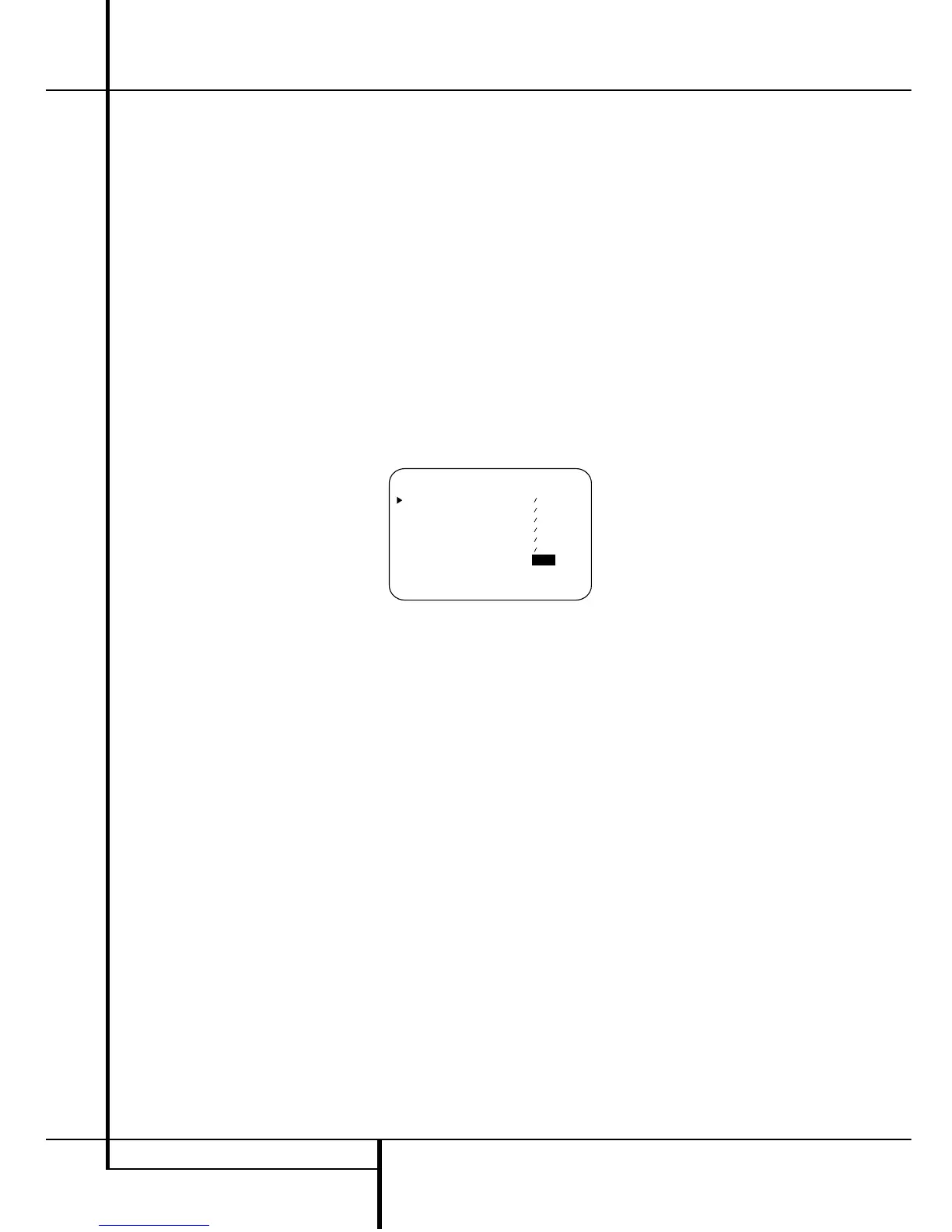
ADJUST menu (Figure 8).
Figure 8
Once the menu appears on your video screen,
use the
⁄/¤ buttons
D
to move the on-screen
› cursor so that it is next to the channel that you
wish to adjust. Then, use the
‹/› buttons
E
to raise or lower the output level.
When all adjustments are done, press the
⁄/¤
buttons
D
to move the on-screen › cursor so
that it is next to RETURN TO MENU
and then press the Set Button
F
if you wish to
go back to the main menu to make other adjust-
ments. If you have no other adjustments to make,
press the OSD button
L
to exit the menu
system.
NOTE: The output levels may be separately
trimmed for each digital and analog surround
mode. If you wish to have different trim levels for a
specific mode, select that mode and then follow the
instructions in the steps shown above.
Changing the levels by the trim adjustment as
described above will automatically change the
level settings in the Output Adjust Menu (Fig. 7,
page 23) correspondingly (and vice versa). With
Stereo and Vmax modes the adjustment proce-
dure described above is the only way to trim the
output level (e.g. to match the Vmax level with
other modes).
6-Channel Direct Input
The AVR 3500 is equipped for future expansion
through the use of optional, external adapters for
formats that the AVR 3500 may not be capable
of processing. When an adapter is connected to
the 6-Channel Direct Input
8
, you may select
it by pressing the 6-Ch Direct Input Selector
. The 6-Channel Direct Input may also be
selected by pressing the Input Source Selector
button
!
on the front panel until the words
6CHappear in the Main Information
Display
N
, and a green LED lights next to 6
CH in the Input Indicators
Ô
.
Note that when the 6-Channel Direct Input is in
use, you may not select a surround mode, as the
external decoder determines processing. In addi-
tion, there is no signal at the record outputs
when the 6-Channel Direct Input is in use, and
the Tone
^*
and Balance
&
controls will
not be effective.
Memory Backup
This product is equipped with a memory backup
system that preserves tuner presets and system
configuration information if the unit is turned off
completely, accidentally unplugged or subjected
to a power outage. This memory will last for
approximately two weeks, after which time all
information must be reentered.
 Loading...