EasyManuals Logo

Harman Kardon AVR 500 Service Manual

Harman Kardon AVR 500
94 pages
To Next Page IconTo Next Page
To Previous Page IconTo Previous Page
Page #5 background imageLoading...
Page #5 background image
1. lnspect all lead dress to make certain that
leads are not pinched or that hardware is not
lodged between the chassis and other metal
parts in the unit.
2. Be sure that any protective devices such as
nonmetallic control knobs, insulating fish-
papers, cabinet backs, adjustment and
compartment covers or shields, isolation
resistor-capacity networks, mechanical
insulators, etc. Which were removed for the
servicing are properly re-installed.
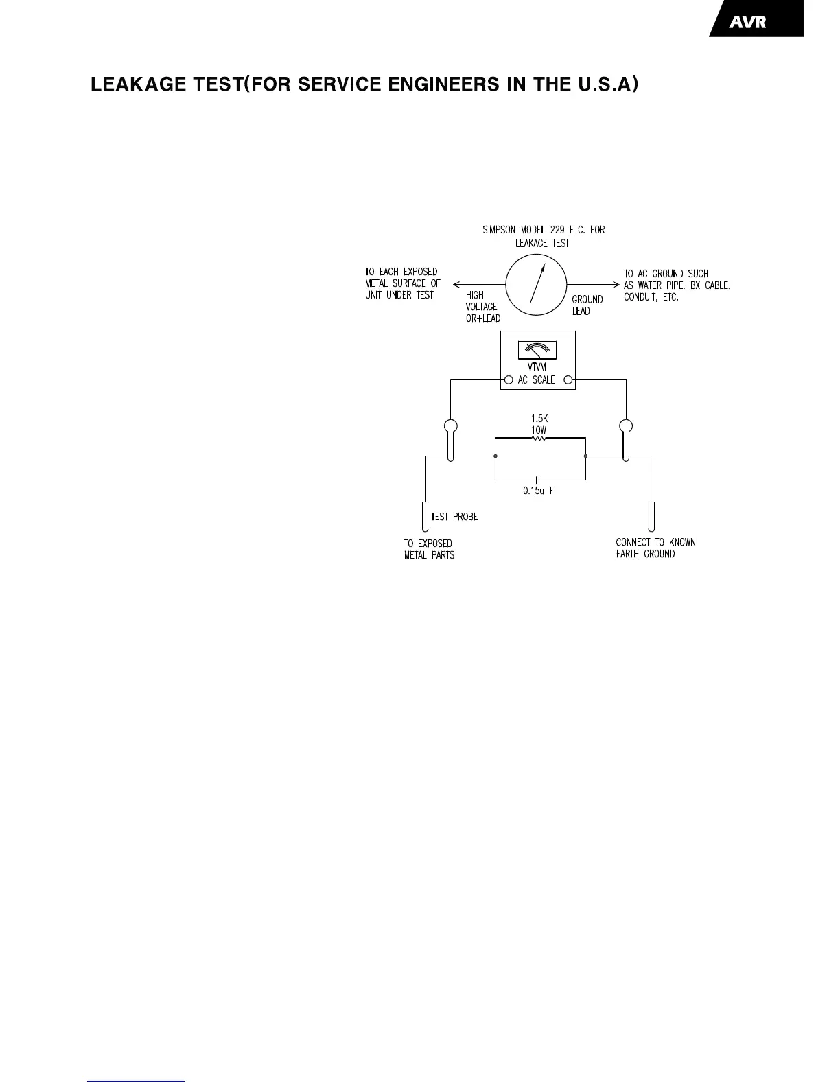
Before returning the unit to the user, perform the following safety checks :
3. Be sure that no shock hazard exists ; check for leakage
current using Simpson Model 229 Leakage Tester, standard
equipment item No. 21641, RCA Model WT540A or use
alternate method as follows : Plug the power cord directly
Into a 120 volt AC receptacle (do not use an Isolation
Transformer for this test). Using two clip leads, connect a
1500 ohms, 10watt Resistor paralleled by a 0.15uF capacitor, in series with all exposed metal cabinet parts and a known earth ground, such
as a water pipe or conduit. Use a VTVM or VOM with 1000 ohms per volt, or higher sensitivity to measure the AC voltage drop across the
resistor. (See diagram) Move the resistor connection to each exposed metal part having a return path to the chassis (antenna, metal, be
performed with the 0.35 volt RMS or more is excessive and indicates a potential shock hazard which must be corrected before returning the
unit to the owner.
-5-
500

Table of Contents

Other manuals for Harman Kardon AVR 500

Questions and Answers:

Question and Answer IconNeed help?

Do you have a question about the Harman Kardon AVR 500 and is the answer not in the manual?

Harman Kardon AVR 500 Specifications

Audio Specifications IconAudio Specifications
continuous average power (FTC)80 Watts per channel, 20Hz–20kHz, @ < 0.07% THD, both channels driven into 8 ohms
power per individual channel (Front L&R channels)70 Watts per channel, @ < 0.07% THD, 20Hz–20kHz into 8 ohms
power per individual channel (Center channel)70 Watts, @ < 0.07% THD, 20Hz–20kHz into 8 ohms
power per individual channel (Surround channels)70 Watts per channel, @ < 0.07% THD, 20Hz–20kHz into 8 ohms
input sensitivity/impedance200mV/47 kohms
signal-to-noise ratio (IHF-A)95dB
frequency response10Hz–100kHz
high instantaneous current capability (HCC)±45 Amps
rise time16 µsec
slew rate40V/µsec
FM Tuner Specifications IconFM Tuner Specifications
frequency range87.5–108MHz
usable sensitivity IHF1.3 µV/13.2dBf
signal-to-noise ratio mono/stereo70/68dB
distortion mono/stereo0.3/0.3%
stereo separation40dB @ 1kHz
selectivity±400kHz, 65dB
image rejection80dB
IF rejection90dB
tuner output level500mV @ 1kHz, ±75kHz Dev
AM Tuner Specifications IconAM Tuner Specifications
frequency range520–1710kHz
signal-to-noise ratio45dB
usable sensitivity loop500µV
distortion0.8% @ 1kHz, 50% Mod
selectivity±10kHz, 30dB
Video Specifications IconVideo Specifications
video formatNTSC
input level/impedance1Vp-p/75 ohms
output level/impedance1Vp-p/75 ohms
video frequency response10Hz–8MHz (–3dB)
General Specifications IconGeneral Specifications
power requirementAC 120V/60Hz
power consumption78W idle, 694W maximum (2 channels driven)
width17.3 inches (440mm)
height6.5 inches (165mm)
depth17.1 inches (435mm)
weight34 lb (15.4 kg)

Related product manuals