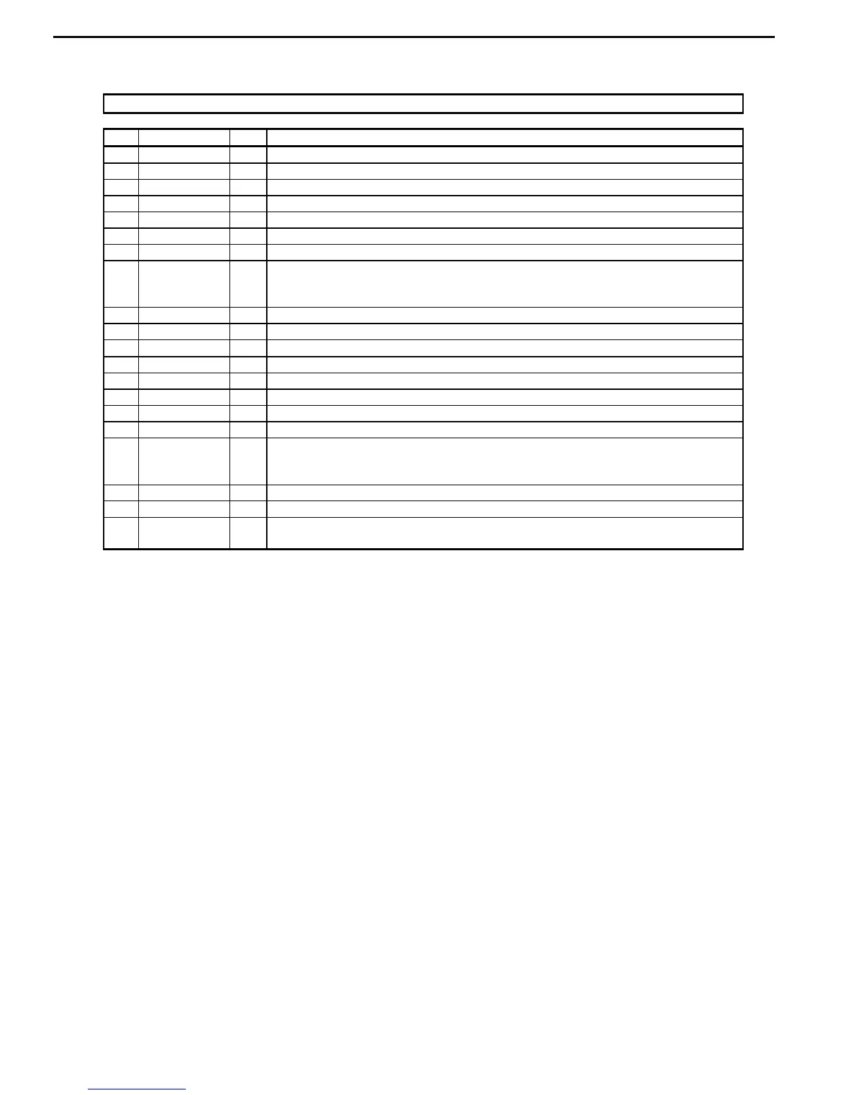
PIN/FUNCTION
No. Pin Name I/O Function
1 LOUT1- O DAC1 Lch Negative Analog Output Pin
2 LOUT1+ O DAC1 Lch Positive Analog Output Pin
3 DZFL2 O DAC2 Lch Zero Input Detect Pin
4 DZFR1 O DAC1 Rch Zero Input Detect Pin
5 DZFL1 O DAC1 Lch Zero Input Detect Pin
6 CAD0 I Chip Address 0 Pin
7 CAD1 I Chip Address 1 Pin
8 PDN I Power-Down & Reset Pin
When “L”, the AK4356 is powered-down and the control registers are reset to
default state. If the state of CAD0-1 changes, then the AK4356 must be reset by PDN.
9 BICK I Audio Serial Data Clock Pin
10 MCLK I Master Clock Input Pin
11 DVDD -
Digital Power Supply Pin, +4.75~+5.25V
12 DVSS - Digital Ground Pin
13 SDTI1 I DAC1 Audio Serial Data Input Pin
14 SDTI2 I DAC2 Audio Serial Data Input Pin
15 SDTI3 I DAC3 Audio Serial Data Input Pin
16 LRCK I Audio Input Channel Clock Pin
17 SMUTE I Soft Mute Pin (Note)
When this pin goes to “H”, soft mute cycle is initialized.
When returning to “L”, the output mute releases.
18 CCLK I Control Data Clock Pin
19 CDTI I Control Data Input Pin
20 CSN I Chip Select Pin
This pin should be held to “H” except for access.
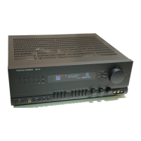
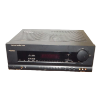
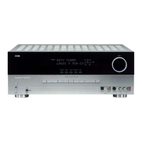
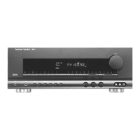
AVR125
harman/kardon

 Loading...