No. Pin Name I/O Function
21 DFS0 I Double Speed Sampling Mode 0 Pin (Note)
“L”: Normal Speed, “H”: Double Speed at DFS1 bit = “0”.
22 CKS0 I Input Clock Select 0 Pin (Note)
23 CKS1 I Input Clock Select 1 Pin (Note)
24 CKS2 I Input Clock Select 2 Pin (Note)
25 DIF0 I Audio Data Interface Format 0 Pin (Note)
26 DIF1 I Audio Data Interface Format 1 Pin (Note)
27 DIF2 I Audio Data Interface Format 2 Pin (Note)
28 DZFE I Zero Input Detect Enable Pin (Note)
29 DZFR3 O DAC3 Rch Zero Input Detect Pin
30 DZFL3 O DAC3 Lch Zero Input Detect Pin
31 DZFR2 O DAC2 Rch Zero Input Detect Pin
32 VREFH I Positive Voltage Reference Input Pin, AVDD
33 AVDD - Analog Power Supply Pin
34 AVSS -
Analog Ground Pin, +4.75~+5.25V
35 ROUT3- O DAC3 Rch Negative Analog Output Pin
36 ROUT3+ O DAC3 Rch Positive Analog Output Pin
37 LOUT3- O DAC3 Lch Negative Analog Output Pin
38 LOUT3+ O DAC3 Lch Positive Analog Output Pin
39 ROUT2- O DAC2 Rch Negative Analog Output Pin
40 ROUT2+ O DAC2 Rch Positive Analog Output Pin
41 LOUT2- O DAC2 Lch Negative Analog Output Pin
42 LOUT2+ O DAC2 Lch Positive Analog Output Pin
43 ROUT1- O DAC1 Rch Negative Analog Output Pin
44 ROUT1+ O DAC1 Rch Positive Analog Output Pin
Note:SMUTE, DFS0, CKS0, CKS1, CKS2, DIF0, DIF1, DIF2, DZFE pins are ORed with serial control register.
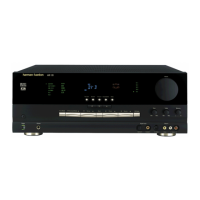
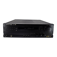
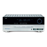
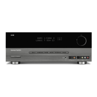
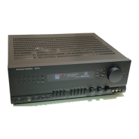
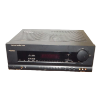
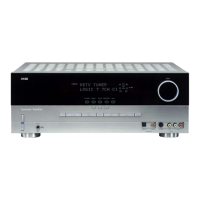
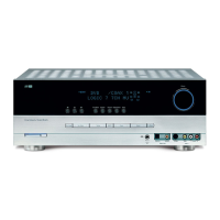
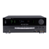
AVR125
harman/kardon
 Loading...
