EasyManua.ls Logo

Harman Kardon AVR135 User Manual

Harman Kardon AVR135
115 pages
To Next Page IconTo Next Page
Page #1 background imageLoading...
Page #1 background image
harman/kardon
AVR135
6 X 40W 6.1 CHANNEL A/V RECEIVER
SERVICE MANUAL
CONTENTS
ESD WARNING……………………………….2
LEAKAGE TESTING……………….…..…....3
BASIC SPECIFICATIONS…………………..4
FRONT PANEL CONTROLS………..…..…..5
REAR PANEL CONNECTIONS………….…7
REMOTE CONTROL FUNCTIONS.…….….9
CONNECTIONS………………………….…12
OPERATION………………………...………14
TROUBLESHOOTING GUIDE…...……..…20
PROCESSOR RESET……………….….…..20
DISASSEMBLY…………………….………...21
UNIT EXPLODED VIEW…………..…….…..24
AMP BIAS ADJUSTMENT……………….…25
TECH TIP HK2003-01…...….….………..…26
BLOCK DIAGRAM…………………………..27
ELECTRICAL PARTS LIST………….……..28
SEMICONDUCTOR PINOUTS…….………61
PCB DRAWINGS………………….………..102
SCHEMATICS………………………………108
WIRING DIAGRAM………….………….…..114
PACKAGING…………………………….….115
harman/kardon, Inc.
250 Crossways Park Dr.
Woodbury, New York 11797
Rev2 1/2006

Table of Contents

Question and Answer IconNeed help?

Do you have a question about the Harman Kardon AVR135 and is the answer not in the manual?

Harman Kardon AVR135 Specifications

General IconGeneral
BrandHarman Kardon
ModelAVR135
CategoryStereo Receiver
LanguageEnglish

Summary

ELECTROSTATICALLY SENSITIVE (ES) DEVICES

Handling Precautions for ES Devices

Techniques to prevent component damage from static electricity.

Product Safety Notice

Important safety information regarding component replacement.

SAFETY PRECAUTIONS

Leakage Current Check

Procedure and limit for measuring leakage current to prevent shock hazards.

TECHNICAL SPECIFICATIONS

Audio Section Specifications

Detailed specifications for the audio performance of the receiver.

Tuner Section Specifications

Detailed specifications for the AM and FM tuner sections.

Video Section Specifications

Detailed specifications for the video processing capabilities.

General Specifications

Overall specifications including power, dimensions, and weight.

FRONT-PANEL CONTROLS

Power and Speaker Controls

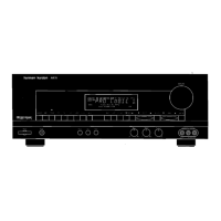
Buttons for power, standby, speaker selection, and headphone jack.

REAR-PANEL CONNECTIONS

REMOTE CONTROL FUNCTIONS

Power and Source Selection

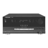
Buttons for power, input selection, and tuner band.

Basic Operation

Powering On/Off and Source Selection

Steps for turning the unit on/off and selecting input sources.

INSTALLATION AND CONNECTIONS

System Setup and Audio Connections

Steps for unit placement, audio source, and speaker connections.

OPERATION

Basic Unit Operation

Turning unit on/off, source selection, volume, and surround modes.

OPERATION DETAILS

TROUBLESHOOTING GUIDE

Common Symptoms and Solutions

Table of common issues, causes, and solutions.

Processor Reset Procedure

Steps to reset system memory and clear configurations.

DISASSEMBLY PROCEDURES

AVR135 EXPLODED VIEW

AMPLIFIER SECTION BIAS ADJUSTMENT

Adjustment Procedure and Settings

Conditions, standard values, and settings for amplifier bias adjustment.

TECH TIPS

Common Service Problems and Solutions

Tips for troubleshooting common issues like memory loss.

Backup Memory Component Replacement

Identifies components to check and replace for memory retention.

AVR135 ELECTRICAL PARTS LIST

WIRING DIAGRAM

Wiring Diagram

Diagram showing connections between major assemblies and PCBs.

Related product manuals