5. Disconnect the board to board connector between and connector (CN23) on the XM PCB (42) and connector (BN17-
12P) on the iPod PCB (39-2).
6. Remove 1 screw (S15) and then remove the XM PCB (42).
12 HDMI PCB (47) REMOVAL
1. Remove the Top-cabinet, referring to the previous step 1.
2. Disconnect the card cable between connector (CN45-7P) on the HDMI PCB (47) and connector (CN45-7P) on the
Video PCB (41).
3. Remove 3 screws (S15) and then remove the HDMI PCB (47).
13 RS232 PCB (37-7) REMOVAL
1. Remove the Top-cabinet, referring to the previous step 1.
2. Remove the Video PCB (41), referring to the previous step 9.
3. Disconnect the card cable between connector (CN47) on the RS232 PCB (37-7) and connector (CN47-7) on the iPod
PCB (39-2).
4. Remove 2 screws and then remove the RS232 PCB (37-7).
14 INPUT PCB (39-1) REMOVAL
1. Remove the Top-cabinet, referring to the previous step 1.
2. Remove the Tuner module (43), referring to the previous step 8.
3. Remove the Video PCB (41), referring to the previous step 9.
4. Remove the iPod PCB (39-2), referring to the previous step 10.
5. Remove the XM PCB (42), referring to the previous step 11.
6. Remove the HDMI PCB (47), referring to the previous step 12.
7. Disconnect connector (CN20) on the the Input PCB (39-1) from the lead wire (BN20-5P) on the Regulator PCB
(B)(40-5).
8. Disconnect connector (CN22) on the Input PCB (39-1) from the lead wire (BN22-6P) on the Phone PCB (37-5).
9. Disconnect connector (CN18) on the Input PCB (39-1) from the lead wire (BN18-5P) on the Phone PCB (37-5).
10. Disconnect connector (CN10) on the Input PCB (39-1) from the lead wire (BN10-4P) on the Volume PCB (37-6).
11. Disconnect the card cable between connector (CN12-21p) on the Input PCB (39-1) and connector (CN12-21p) on the
main PCB (38-1)
12. Disconnect the card cable between connector (CN11-13p) on the Input PCB (39-1) and connector (CN11) on the main
PCB (38-1)
13. Disconnect the card cable between connector (CN72) on the Input PCB (39-1) and connector (CN72-17p) on the Fip
PCB (37-1)
14. Remove 11 screws (S8,S15) and then remove the Input PCB (39-1).
15 POWER TRANS (36) & POWER PCB ASS’Y(40) REMOVAL
1. Remove the Top-cabinet, referring to the previous step 1.
2. Disconnect lead wire of the Power Trans (36) from connector (CN91-3P) on the Main PCB (38-1)
3. Disconnect connector (CN19-3P,CN20-4P) on TRANS PCB (40-3) from the lead wire (BN19-3P,BN20-4P) on the in
PCB (38-1).
4. Disconnect the lead wire (BN96-8P) on the Power PCB (40-4) from connector (CN96) on the Regulator PCB (B)(40-5).
5. Disconnect the lead wire (BN99-8P) on the Power PCB (40-4) from connector (CN99) on the Regulator PCB (A)(40-2).
6. Disconnect connector (CN81) on the Trans PCB (40-4) from the lead wire (BN81-8P) on the Fip PCB (37-1).
7. Remove 4 Trans screws (S9) and then remove the Power Trans (36) & Power PCB ASS’Y(40) REMOVAL .
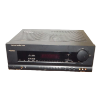
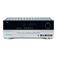
AVR147 harman/kardon
 Loading...