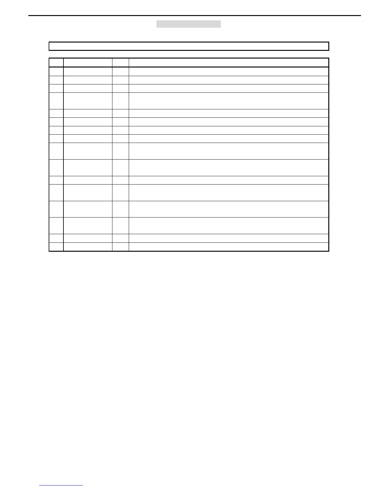
ASAHI KASEI [AK5381]
R
PIN / FUNCTION
No. Pin Name I/O Function
1 AINR I Rch Analog Input Pin
2 AINL I Lch Analog Input Pin
3 CKS1 I Mode Select 1 Pin
4 VCOM O
Common Voltage Output Pin, VA/2
Bias voltage of ADC input.
5 AGND - Analog Ground Pin
6 VA - Analog Power Supply Pin, 4.5 ∼ 5.5V
7 VD - Digital Power Supply Pin, 2.7 ∼ 5.5V(fs=4k ∼ 48kHz), 3.0 ∼ 5.5V(fs=48k ∼ 96kHz)
8 DGND - Digital Ground Pin
9 SDTO O
Audio Serial Data Output Pin
“L” Output at Power-down mode.
10 LRCK I/O
Output Channel Clock Pin
“L” Output in Master Mode at Power-down mode.
11 MCLK I Master Clock Input Pin
12 SCLK I/O
Audio Serial Data Clock Pin
“L” Output in Master Mode at Power-down mode.
13 PDN I
Power Down Mode Pin
“H”: Power up, “L”: Power down
14 DIF I
Audio Interface Format Pin
“H” : 24bit I
2
S Compatible, “L” : 24bit MSB justified
15 CKS2 I Mode Select 2 Pin
16 CKS0 I Mode Select 0 Pin
Note: All digital input pins should not be left floating.
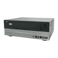
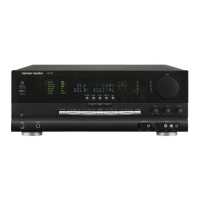
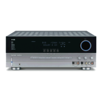
AVR335 harman/kardon
 Loading...