16
3-90-08101R23_06/13
Wall Control Wiring
TheWallControlsendsandreceivesinformationfromthe
controlboardthrougha4wireDatacomcable.Thereisa100’
lengthofthiscablesuppliedwiththefurnace.100’lengthsof
thiscablecanalsobeorderedseparately,part#3-20-02583.
Alternately,anyDatacomcable-CAT3-2twistedpair24ga
solidwirecanbeacquiredatalocalelectricalsupplyhouse.
AlsoanyCAT3-24ga.solidwire2,3,or4paircablecanbe
usedbecausetheyallhavethesamepaircolorcombinations.
Themaximumlengthofwallcontrolwiringis100feet.
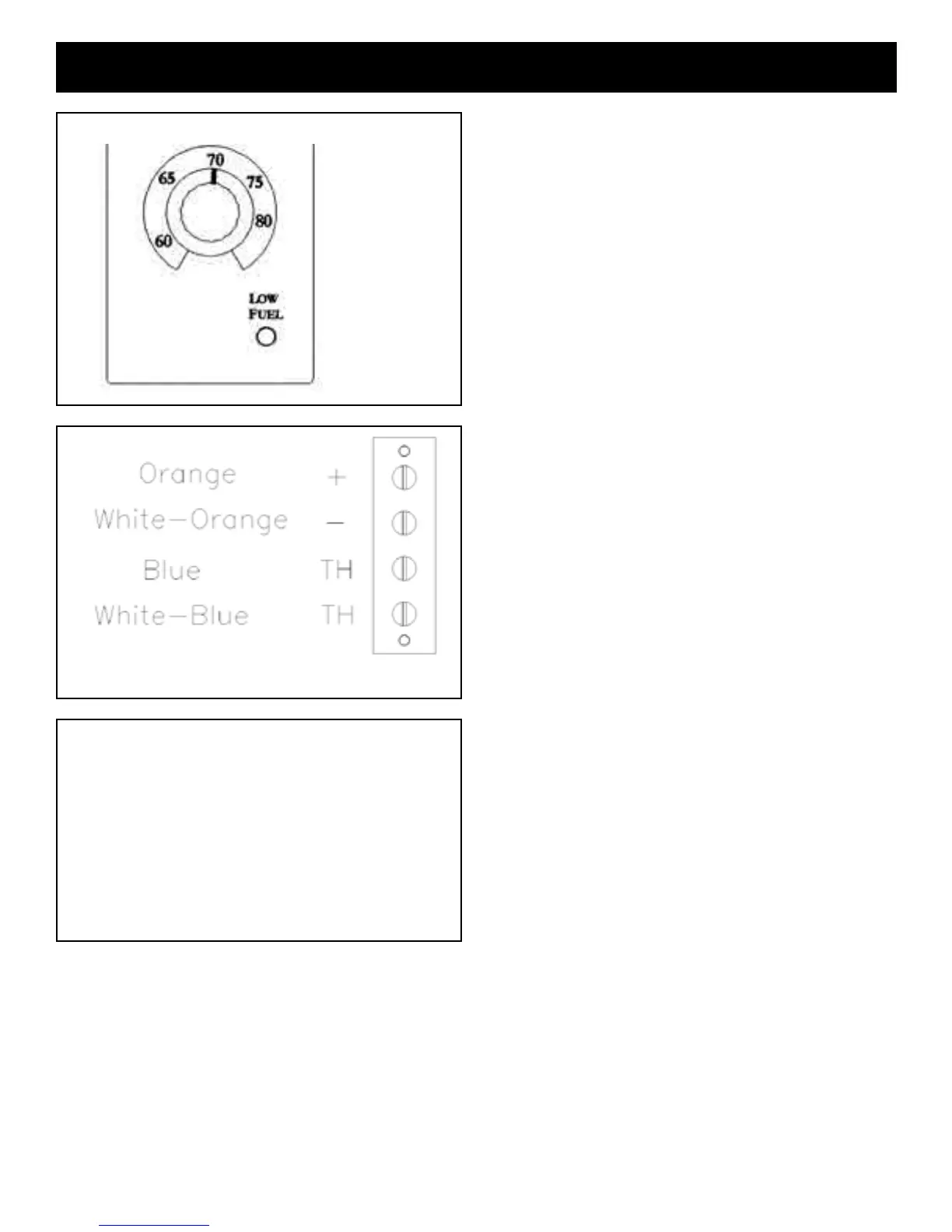
Thefurnaceconnectingpointisa4polescrewterminalblock
onthesideofthehopperjustaroundthecornertotheright
of the control. Follow the wiring instructions on the label
alongsidetheterminalblock.SeeFig.31.
CAUTION:Withthissmallgaugeofwire,caremustbetaken
nottoovertightentheterminalscrewsthus,breakingthewire.
Therearetie-wrapholesin thefaceofthehopperaprox.
every6”tokeepthecablesecureandoutoftheway.
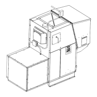
The Wall Control is made to t on a standard wall case
electricalbox. Itcould also bemounted directly toa stud
using2drywallscrews.Ineithercasethescrewsshouldbe
turnedinandtestedforasnugtwhentheWallControlis
sliddownoverthescrews.TheWallControlonlyhangson
thescrewssoagoodtisimportant.
Remove the Wall Control and make the Datacom cable
connectionswiththeUYauto splicersprovided.DO NOT
STRIP THE WIRES.Followingthewiringdiagramonthe
insideoftheWallControlmakeeachsplice.SeeFig.32.
Insertthetwomatchingcolorwiresfullyintothetwoholes
ofoneoftheUYconnectors.ApairofstandardChannel-
lockpliersworksideallytosqueezetheraisedbuttondown
intotheUYconnectorbody.ExtraUYconnectorscanbe
purchased.Part#3-20-00200
NOTE:Apairofneedlenosepliersmaybehelpfultoinsert
theBLUET-statwiresfullyintotheconnector.Visuallyinspect
toseethatthewiresarefullyinsertedbeforesqueezingthe
UYsplicer.
Installation
Orange-Red(+LED)
Orange/White-WhiteorBlack(-LED)
Blue-Blue(Tstat)
Blue/White-Blue(Tstat)
DatacomWallControl
Cable
Fig. 32
Fig. 30
Fig. 31
 Loading...