EasyManua.ls Logo

Harmar Mobility AL215 Axis I User Manual

Harmar Mobility AL215 Axis I
44 pages
To Next Page IconTo Next Page
Page #1 background imageLoading...
Page #1 background image
Read and understand this manual thoroughly before attempting
to install or operate the lift. If you have any questions, please
contact your Authorized Harmar Dealer or Harmar’s Technical
Service Department.
P 800-833-0478 | F 866-234-5680 | tech@harmar.com
TEC0091 2016JUN30 P/N: 630-00076-Rev A
Dealer Name & Contact Information:
Serial # of Your Lift:
Inside Lifts
Installation & Owners Manual
www.harmar.com | 800-833-0478
AL215 Axis I
Single Axis Inside Lift
Capacity: 250 lbs.
AL425 Axis II
2-Axis Inside Lift
Capacity: 400 lbs.
AL225 Axis II Lift
2-Axis Inside Lift
Capacity: 250 lbs.
AL435 Axis III
3-Axis Inside Lift
Capacity: 400 lbs.
AL435T Axis III
Truck Lift
Capacity: 400 lbs.
Question and Answer IconNeed help?

Do you have a question about the Harmar Mobility AL215 Axis I and is the answer not in the manual?

Harmar Mobility AL215 Axis I Specifications

General IconGeneral
BrandHarmar Mobility
ModelAL215 Axis I
CategoryLifting Systems
LanguageEnglish

Summary

SAFETY

Operator Instruction Required

Ensure proper instruction from dealer before operating the lift.

Pre-Use Component Inspection

Regularly inspect lift components for wear, looseness, or damage.

Lifting Strap Security

Secure and taut lifting strap prevents swinging and damage.

Keep Clear During Operation

Keep hands and feet clear of the chair/scooter during loading/unloading.

Secure Load During Transport

Secure chair/scooter on floor during transport to prevent movement.

MAINTENANCE

Lifting Strap Checks

Always check the lifting strap for wear or damage before using the lift.

INSTALLER PREPARATION

Manual Review Prior to Installation

Thoroughly read and understand the manual before installation or operation.

Seek Expert Assistance

Seek assistance from experts if any part of installation or operation is unclear.

INSTALLER INSTALLATION

Vehicle Wiring Procedure

Follow wiring instructions carefully to avoid operational problems.

Battery Connection and Harness Routing

Connect black wire to negative terminal and route harness.

Final Battery Connection

Connect the red wire to the positive battery terminal.

Trial Fit Procedure Steps

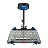
Position base, fold seat, simulate dimensions and range of motion.

Flat Floor Base Installation

Drill holes and fasten base to a flat vehicle floor.

Drill Pilot Holes for Base Mounting

Drill 3/8" holes at marked locations after checking for obstructions.

Fastening the Base to the Floor

Secure the base to the vehicle floor using supplied hardware.

3rd Row Folding Seat Base Installation

Install base for vehicles with 3rd-row folding seats.

Vertical Joiner Placement and Height

Position joiners and set height relative to vehicle threshold.

Drilling for 3rd Row Seats

Drill holes through floor and wall for 3/8" hardware and bolts.

Truck Bed Base Installation

Install base in truck bed, ensuring clearance and proper alignment.

Truck Bed Base Placement

Position base in truck bed corner with at least 1" clearance.

Leg Extension Installation

Insert leg extensions and extend them parallel to the bumper.

Pre-Drilling Recommendations

Estimate hole distances and check for frame or obstructions.

Pilot Hole Verification and Drilling

Verify pilot hole positions and drill 3/8" holes through bed and frame.

Inspect Pilot Hole Locations

Inspect pilot hole locations to avoid vehicle components like gas tank.

Incorporating Truck Frame Rails

Incorporate frame rails for lifting heavier chairs and scooters.

Lift Installation onto Base

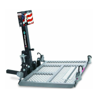
Install the lift onto the base after securing the base cover.

Lifting Arm Attachment

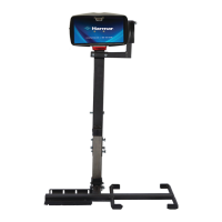
Mount the lifting arm according to the specific lift model.

INSTALLER LIFT ADJUSTMENTS

INSTALLER TROUBLE SHOOTING

INSTALLER ELECTRICAL

Related product manuals