Inside Lifts - Installation & Owner’s Manual TEC0091 2016JUN30 P/N: 630-00076-Rev A |
| www.harmar.com | 800-833-0478
© 2016 Harmar All Rights Reserved
15
INSTALLER
VEHICLE’s THRESHOLD
SED FOR SEAT
TACHMENT
OINT
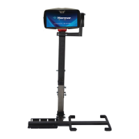
TELESCOPING LEG
SWIVEL
LEG
VEHICLE’s
THRESHOLD
LLAWs’ELCIHEV
CHOOSE
HOLE FOR
CLOSEST
TO WALL
POSITION
1" or
OBTAIN
DISTANCE
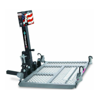
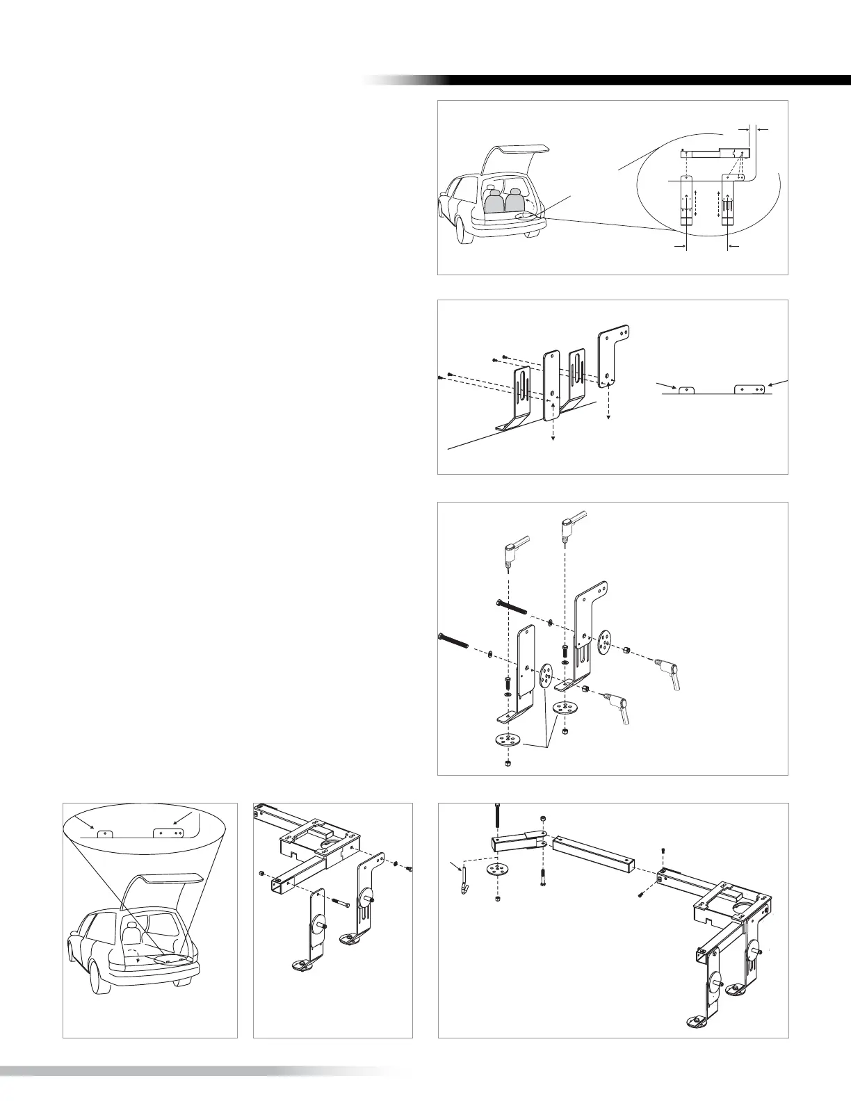
Foldupthird
rowseating
Figure 15-1
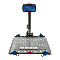
PLACE ON
WELL FLOOR
THRESHOLD
Figure 15-2
INSTALLATION
WASHERS
Drilltwo 3/8"h
through back well
wall using joiners
as templateto
acceptfully
threaded
3/8" bolts.
Figure 15-3
Figure 15- 4 Figure 15-5 Figure 15- 6
BASE INSTALLATION:
3
RD
ROW FOLDING SEATS
1. Place vertical joiners on back wall of seating
well corner. [Figure 15-1] Use base as template for
position.
2. Establish height by having mounting holes
show over threshhold. [Figure 15-2] Attach joiners,
using small screws provided, to lock height.
3. Preferred Installation. Mandatory when lifting
heavier payloads.
• Drill two 3/8” holes in floor of well using
joiners as template. Fasten 3/8” hardware
(x2). [Figure 15-3]
• PLUS Drill two 3/8” holes through back well
wall using joiners as template to accept full-
threaded 3/8” bolts.
VERIFY THAT ALL MATING SURFACES ARE FLUSH.
4. Fold third-row seating back into well. Verify
vertical joiner mount holes are above threshold.
[Figure 15-4]
5. Attach vertical joiners to base using supplied
hardware as indicated. [Figure 15-5]
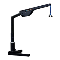
6. Insert telescoping leg. Attach swivel leg. Drill,
or where possible, use J-hook to seat attachment
point and secure leg. [Figure 15-6]
Tighten all fasteners.
INSTALLATION