Revision C • 10/07
HARRIS CORPORATION
2-22
2 Installation
KSU CARD CONNECTIONS (CONT.)
FUNCTIONAL DESCRIPTION
To enable the control inputs: Mute and Dim, tie this pin to + logic voltage (+5 to +40). When tied to an
isolated device like a talk panel, jumper to pin 7 (+5 volts) to enable the inputs. When tied to a peripheral
device, connect to the peripheral device + voltage pin.
When pulled low, mutes the speaker monitor output and triggers the Mute Relay output. May also turn on
the Warning Tally output, depending upon session file settings.
When pulled low, dims the speaker monitor output and triggers the Dim Relay output.
The Common (C) relay contact output for the Talk, Dim, and Mute Relays. It can be set for active low or high
logic: for an active low output jumper this pin to logic ground; for active high output, jumper this pin to the
+ voltage logic supply. For isolated operation, the ground and/or logic supply should be supplied by the
peripheral device. When used with a remote panel, jumper to pin 3 for active low logic or pin 6 for active
high logic. Relay outputs can sink or source up to 60 volts at 350 mA (combined current).
Connects to Relays Common (pin 10) while mute is active. Output is a N.O. dry contact type that is typically
used to drive a mute indicator or to mute talk and cue speakers.
Connects to Relays Common (pin 10) while dim is active. Output is a N.O. dry contact type that is typically
used to drive a dim indicator or to control a switch to dim talk and cue speakers.
Connects to Relays Common (pin 10) while receiving a talk command. Output is a N.O. dry contact type that
is typically used to drive an indicator or to control an incoming talk speaker switch.
Isolated N.O. dry contacts for control of a warning lamp interface (like the Harris WL-2) when a mute
command is received. Up to 60 volts at 350 mA can be switched through the contacts.
Console logic voltage output source that can deliver up to 300 mA of current for isolated devices. Pins are
paralleled for convenience.
Console logic ground. Should be connected to isolated devices only.
PIN NAME / NUMBER
ENABLE LOGIC INPUTS (+)
(pin 14)
MUTE (-) (pin 8)
DIM (-) (pin 9)
RELAYS COMMON (pin 10)
MUTE RELAY (pin 11)
DIM RELAY (pin 12)
TALK RELAY (pin 13)
WARNING RELAY (pins 4, 5)
+5 VOLT LOGIC SUPPLY
(pins 6 and 7)
LOGIC GND (pins 1, 2, 3)
Control Room and Studio Logic I/O Signal Definitions
(see page 2-13 for a simplified circuit block diagram)
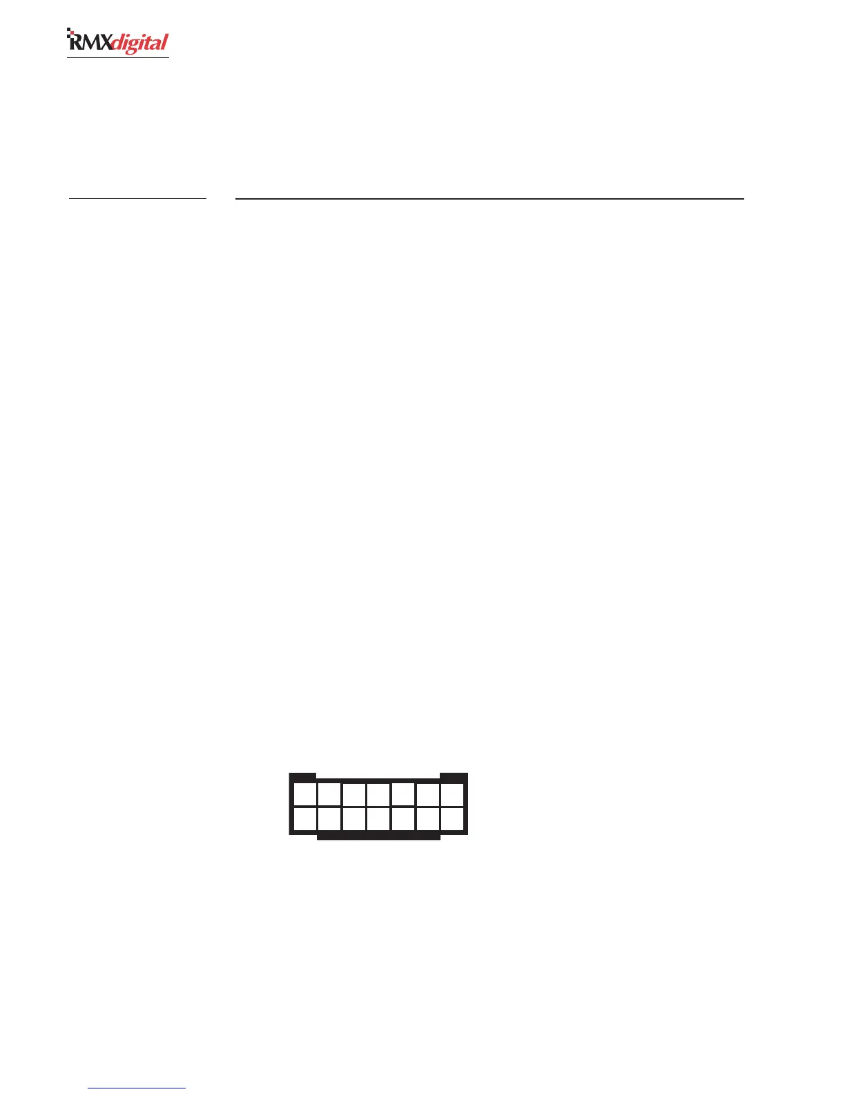
1 2 3 4 5 6 7
8 9 10 11 12 13 14
Pin numbering order,
wire insertion end view,
as plugged into the console
Control Room & Studio Logic
14-Pin Logic Connector
Housing