Revision C • 10/07
HARRIS CORPORATION
2-25
2 Installation
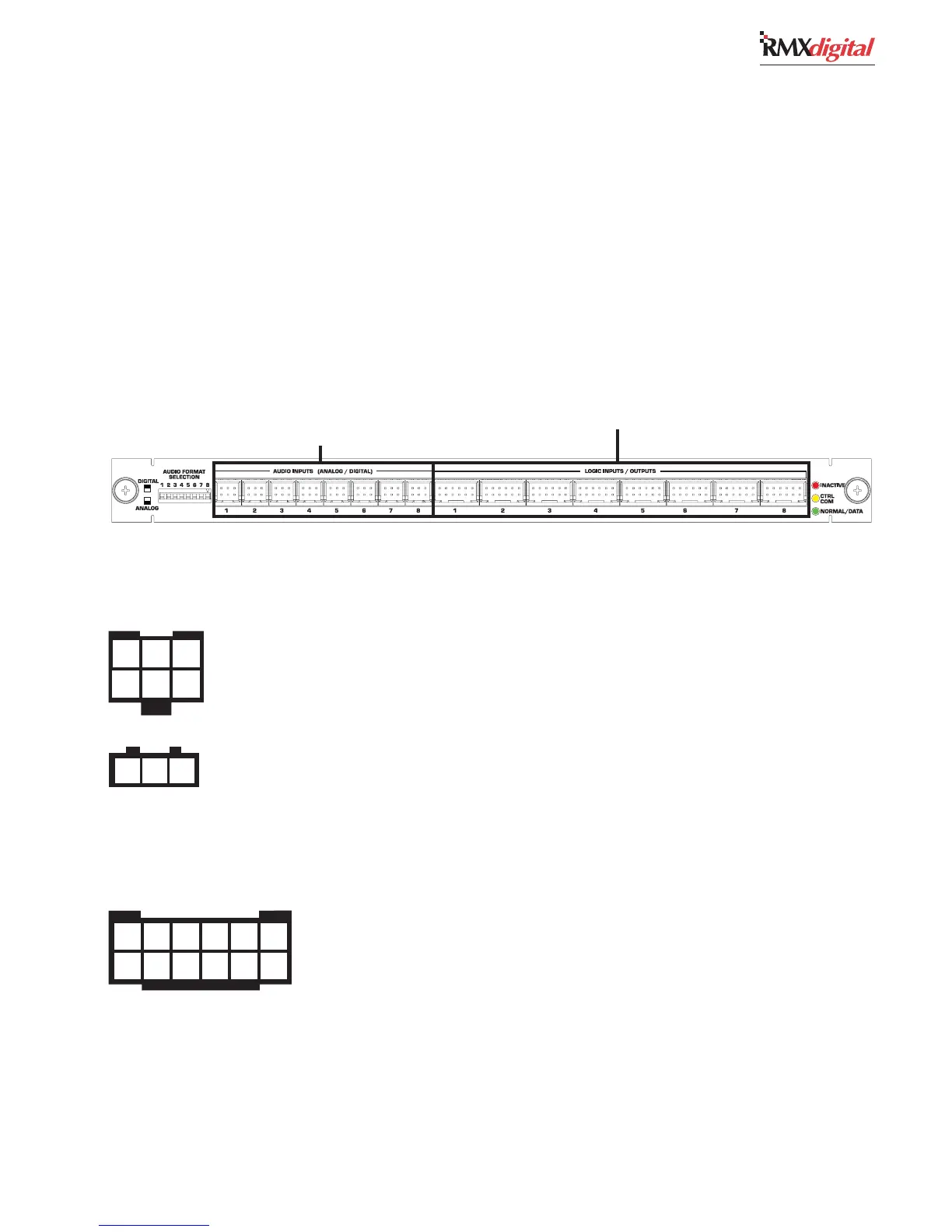
QUICK GUIDE TO THE 8-INPUT EXPANSION CARD CONNECTIONS
The optional 8-Input Expansion card adds eight audio inputs and eight Assignable Logic I/O connections to a DSP
Card. There can be one 8-Input Expansion card added to each DSP card in a console. Since the RMX
d
-4 does not have a
DSP card, an 8-Input Expansion card cannot be used in that size frame.
The eight 6-pin audio connectors are individually set as an analog or a digital input by the eight Audio Format DIP
switches next to audio input 1. Digital signals connect using a 3-pin connector plugged into the back row of pins in the
same orientation as on the KSU card. There is no connection to the front row of pins on a digital signal. Each analog input
uses a 6-pin connector with either one stereo pair or two separate mono signals on the connector. Note that the 6-pin
connectors are reversed from the analog connector orientation on the KSU card.
The eight Assignable Logic I/O connections can be bound to any audio input on this 8-Input Expansion card. See page
2-21 for the Assignable Logic I/O signal summary.
Assignable Analog or
Digital Input Connections (x8)
Assignable Logic I/O Connectors (x8)
FOR AN ANALFOR AN ANAL
FOR AN ANALFOR AN ANAL
FOR AN ANAL
OG INPUT —OG INPUT —
OG INPUT —OG INPUT —
OG INPUT — Set the matching numbered DIP switch toward the board operator to
select analog. Connect one stereo or two mono line level signals to the input using one 6-pin AMP MOD IV
connector. Each input can be trimmed in VMCC for unbalanced -10 dBv connections. Note that these
connectors have reversed orientation from the analog connectors on the KSU Card (the left input is on the
back row of pins).
FOR A DIGITFOR A DIGIT
FOR A DIGITFOR A DIGIT
FOR A DIGIT
AL INPUT —AL INPUT —
AL INPUT —AL INPUT —
AL INPUT — Set the matching numbered DIP switch toward the back of the console to
select digital. Use a 3-pin AMP MOD IV connector to plug an AES/EBU signal into the rear row of pins (the
front row of pins is not used). See page 2-11 on how to connect a S/PDIF signal. The digital connections use
the same orientation as the digital connectors on the KSU Card.
1 2 3
1 2 3
4 5 6
1 2 3 4 5 6
7 8 9 10 11 12
1 - 8 —1 - 8 —
1 - 8 —1 - 8 —
1 - 8 — A peripheral, peripheral control panel or a mic control panel can connect to each 12-pin
connector. For the default logic signals, see page 2-21. For a block diagram of the Assignable Logic
I/O interface, see page 2-13. Each Assignable Logic connection can be bound to an audio input on
this card. See chapter 4 for additional setup and application information.
AUDIO INPUTS 1 - 8
ASSIGNABLE LOGIC I/O