Revision C • 10/07
HARRIS CORPORATION
2-29
2 Installation
COMPLEX LOGIC CONNECTION EXAMPLE
This example shows a peripheral device with complex logic functions (a digital delivery system) connected to
an Assignable Logic I/O connector, using default logic settings. For most peripheral devices, the logic ground and
+5 volt supply connections are not used, but in this example all of the digital delivery system connections are also
isolated. Information on binding the logic to the peripheral’s audio inputs and the channel strip session file
settings for peripherals are covered in chapter 4, RMX
digital
Server and in Appendix A, VMCC.
PIN #PIN #
PIN #PIN #
PIN #
SIGNALSIGNAL
SIGNALSIGNAL
SIGNAL
FUNCTIONFUNCTION
FUNCTIONFUNCTION
FUNCTION
1
LL
LL
L
OGIC GROGIC GR
OGIC GROGIC GR
OGIC GR
OUNDOUND
OUNDOUND
OUND Logic ground
2 CUE INPUT (-) Remote Cue switch input (active low)
3 OFF INPUT (-) Remote Off switch input (active low)
4
ENABLE LENABLE L
ENABLE LENABLE L
ENABLE L
OGIC INPUTOGIC INPUT
OGIC INPUTOGIC INPUT
OGIC INPUT
S (+)S (+)
S (+)S (+)
S (+) Jumper to +VDC to enable switch inputs
5
STST
STST
ST
OP PULSEOP PULSE
OP PULSEOP PULSE
OP PULSE Stop command output, N.O. contact
6
PULSE CPULSE C
PULSE CPULSE C
PULSE C
OMMONOMMON
OMMONOMMON
OMMON Start/Stop Pulse common, C contact
7 +5 VOLT LOGIC SUPPLY 5 volt source
8
READREAD
READREAD
READ
Y INPUT (-)Y INPUT (-)
Y INPUT (-)Y INPUT (-)
Y INPUT (-) Remote Ready switch input (active low)
9
ON INPUT (-)ON INPUT (-)
ON INPUT (-)ON INPUT (-)
ON INPUT (-) Remote On switch input (active low)
10
+5 +5
+5 +5
+5
VV
VV
V
OLOL
OLOL
OL
T LT L
T LT L
T L
OGIC SUPPL
OGIC SUPPL
OGIC SUPPLOGIC SUPPL
OGIC SUPPL
YY
YY
Y 5 volt source to enable switches
11
STST
STST
ST
ARAR
ARAR
AR
T PULSET PULSE
T PULSET PULSE
T PULSE Start command output, N.O. contact
12
+5 +5
+5 +5
+5
VV
VV
V
OLOL
OLOL
OL
T LT L
T LT L
T L
OGIC SUPPLOGIC SUPPL
OGIC SUPPLOGIC SUPPL
OGIC SUPPL
YY
YY
Y 5 volt source for switch tallies
Notes: +VDC is between +5 and +40 VDC.
Outputs can switch voltages up to +60 VDC at 350 mA total
BB
BB
B
oldold
oldold
old indicates connections used in this example.
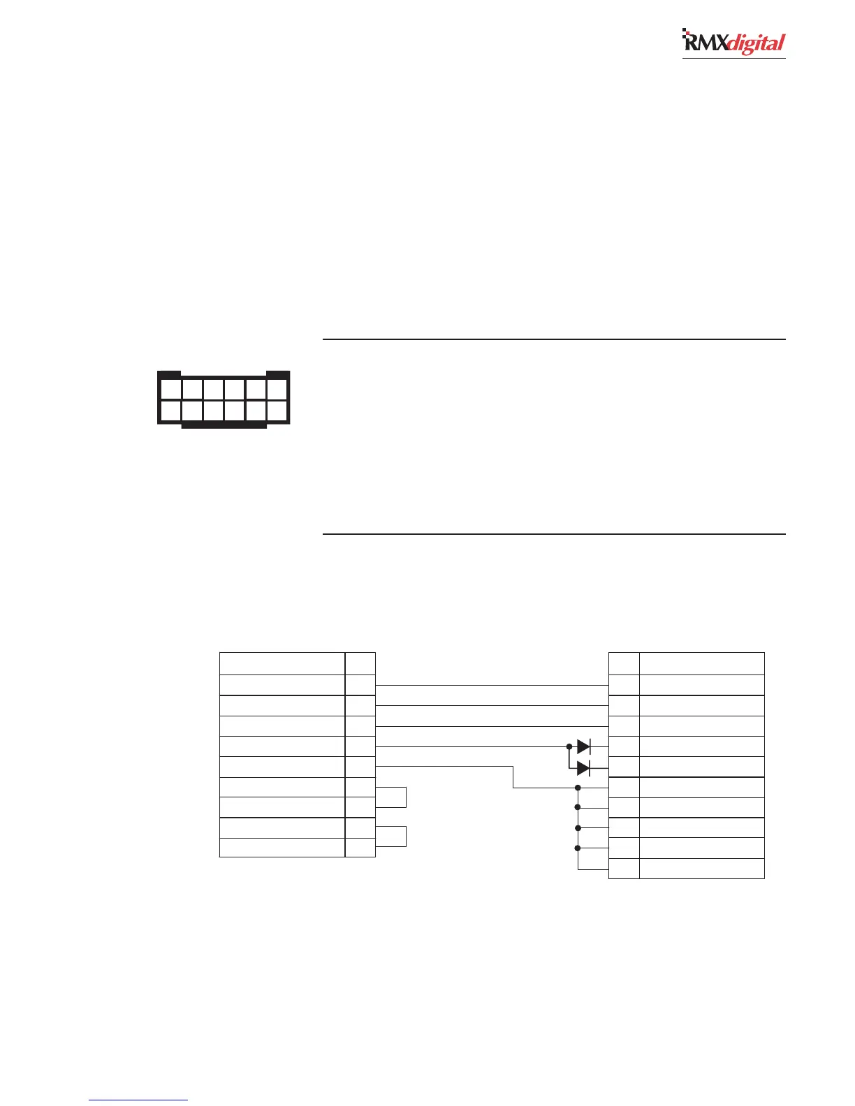
ASSIGNABLE INPUT LOGIC CONNECTOR SIGNAL TABLE
(wire insertion end view)
1 2 3 4 5 6
7 8 9 10 11 12
ASSIGNABLE
LOGIC CONNECTOR
ENCO DADPRO
INTERFACE LOGIC
SIGNAL PIN
PIN SIGNAL
BLK
WHT
BRN
RED
GRN
Start Pulse
Stop Pulse
On (-)
Ready (-)
Logic GND
Enable Logic Inputs (+)
+5 VDC
Pulse Common
+5 VDC
11
5
9
8
1
4
10
6
12
8
7
19
36
16
27
26
37
17
34
Input 0 (+)
Input 1 (+)
Relay 0 N.O.
Relay 1 N.O.
Relay 2 N.O.
Input 0 (-)
Input 1 (-)
Relay 0 common
Relay 1 Common
Relay 2 Common
CR1
CR2
PARTS LIST
Cable: 19-119 (Belden 8445 or equiv.)
Diodes: 11-7 (1N4001 or equiv.)
37-pin DSub: 15-885 (DC 110963-4)
DSub crimp pins: 15-884 (DB-37P)
12-pin MOD IV housing: 14-490 (Tyco-AMP 87922-2)
MOD IV contacts: 15-938-1 (Tyco-AMP 102128-1)