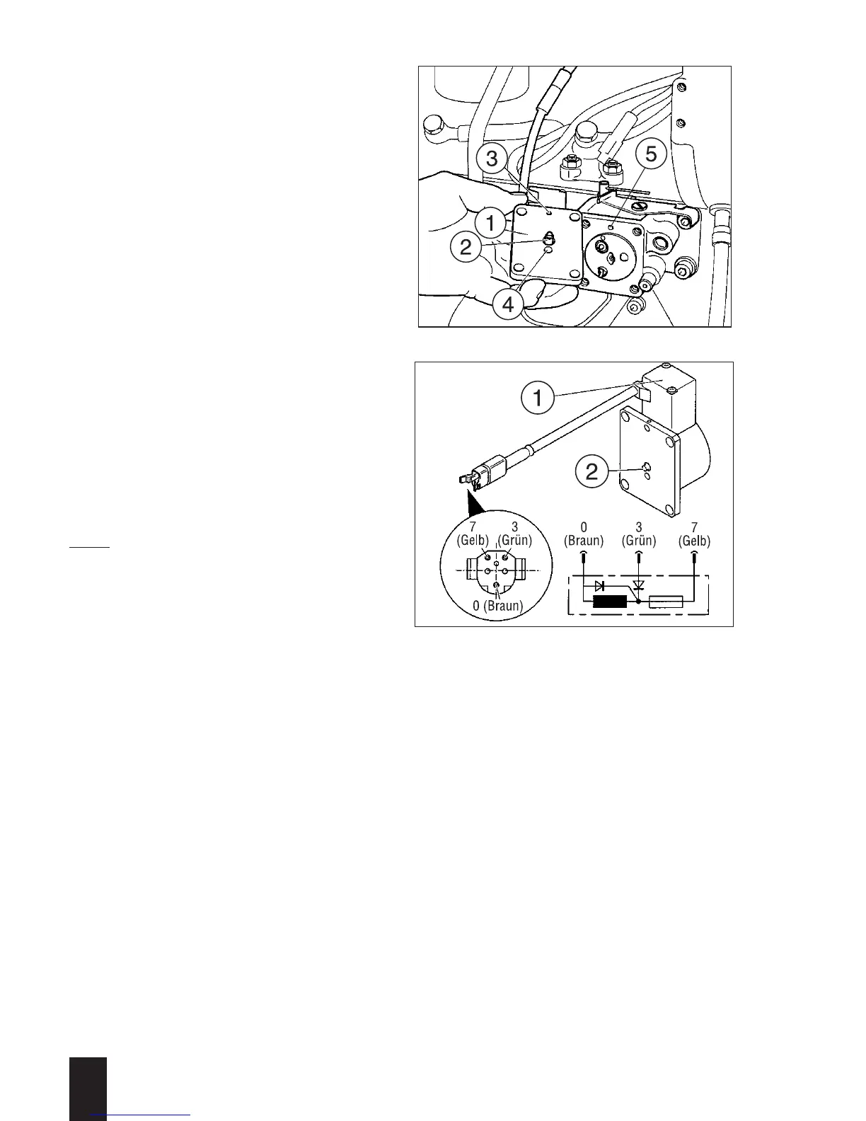
Checking valve solenoid:
(Fig 168)
– without electric control:
– Valve pin 2 is in the rest position;
the connection between bores 3 and 4
is closed.
– Apply the electric current to connection
„7“ (yellow wire):
the valve pin must extend by approx.
6 mm.
F » 15 - 20 N (loading can easily be
overcome with the finger), free passage
between bores 3 and 4.
– Apply the electric current to connection
„3“ (green wire):
the valve pin must extend fully.
F » 30 - 50 N (very difficult to overcome
loading with finger pressure), free pas-
sage between bores 3 and 4.
– If any repairs are made to the wiring,
make sure that the plugs are wired up
correctly (Fig. 169).
Note:
When installing the valve solenoid or
cover (164/4), note the corrct installed
position (this also applies to the gasket);
holes 168/3 and 5 must be aligned.
3
L / M . . 09.96
168
169