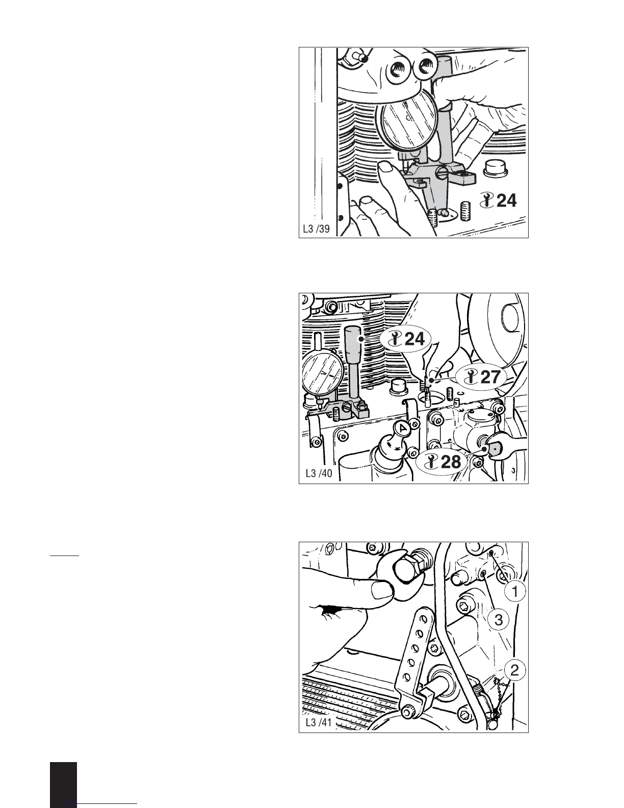
– Remove the second injection pump
(looking from the timing end) and install
measuring device - 24 - in its place (the
ball end on the vertical lever must enga-
ge in the driving slot of the governor
rod); see Fig. 144.
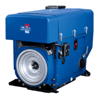
– Loosen the grub screw (146/1).
– Turn the adjusting screw (19 mm across
flats) by 1/8 of a turn counter-clockwise.
– Move the speed control lever to the
starting position.
– Insert locating pin - 27 - into the hollow-
drilled stud bolt, then turn the adjusting
screw slowly clockwise until the locating
pin engages under light pressure in the
corresponding slot of the governor rod;
Figs. 141 and 145.
This determines the „X“ position of the
governor rod.
– In this position, set the dial gauge scale
on the adjusting device precisely to „0“.
– Pull out the locating pin; the needle of
the dial gauge should then move by
0.01 - 0.02 mm.
– Determine the governor rod travel
stated on the type plate (the figure is in
hundredths of a millimetre).
– Turn the injection volume adjusting tool
until the dial gauge shows the control
distance needed. Do not forget the
0.01 - 0.02 mm already indicated by the
dial gauge.
Note:
A minus value (= lower power range) is
obtained by turning the adjusting tool
clockwise, a plus value (higher power) by
turning counter-clockwise.
– Tighten the grub screw (146/1) carefully
to prevent this setting from being lost,
and secure it with lacquer.
3
L / M . . 09.96
144
145
146