33
+ -
GND
+24V
12
12345678910
12
123
1234
GND
24V
BUS
24V
1 234567
12L
GS 9
+24V
+ -
GND
+24V
12
12345678910
12
123
1234
GND
24V
BUS
24V
1 234567
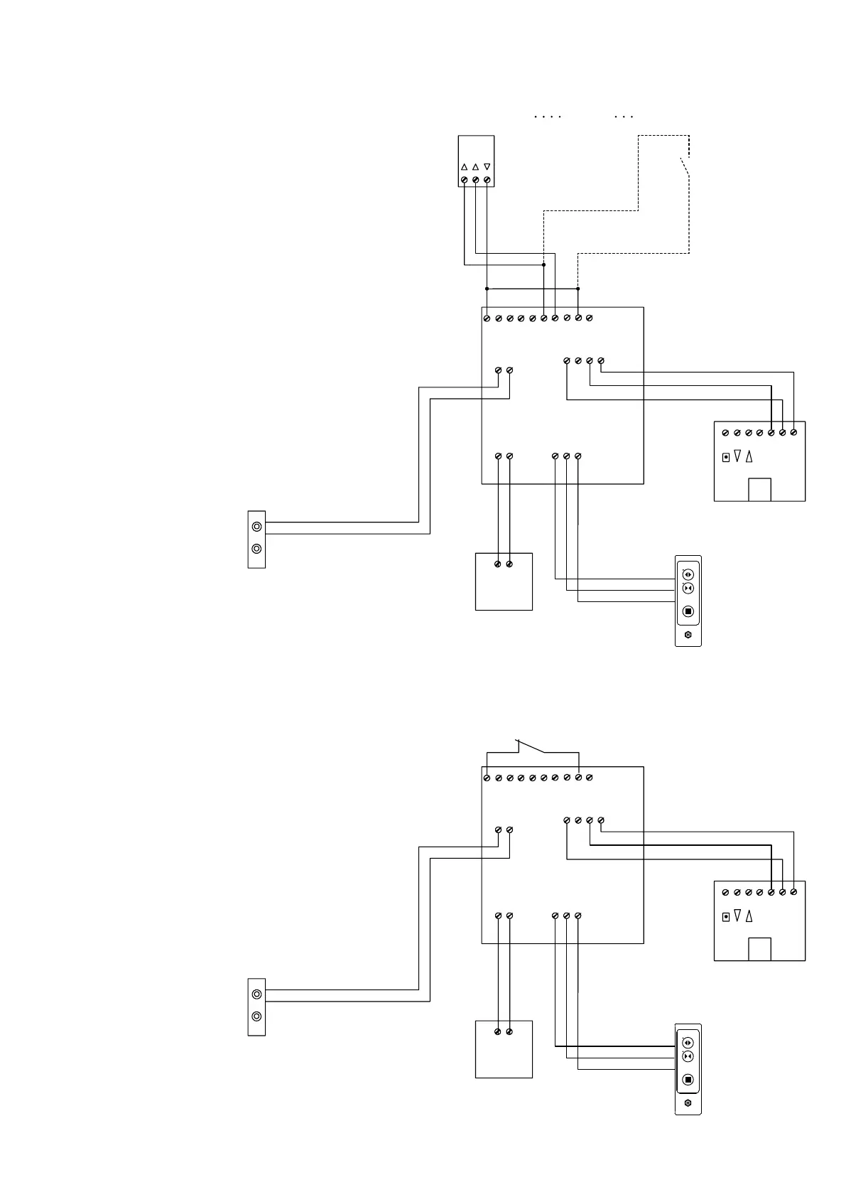
Anschlussplan (Beispiele, Forts.)
Connecting diagram (examples, cont‘d)
Elektrischer Anschluss (Forts.)
Electrical connection (cont‘d)
HS comfort drive + WLAN-Box
mit NOT-AUS-Schalter
HS comfort drive + WLAN box
with EMERGENCY STOP switch
HS comfort drive + WLAN-Box
ohne NOT-AUS-Schalter
HS comfort drive + WLAN box
without EMERGENCY STOP switch
Platine Antriebsmodul
HS/S comfort drive
Circuit board drive module
HS/S comfort drive
Platine Antriebsmodul
HS/S comfort drive
Circuit board drive module
HS/S comfort drive
Hubantrieb
Lift drive
Hubantrieb
Lift drive
HAUTAU-Bus
HAUTAU bus
HAUTAU-Bus
HAUTAU bus
Netzteil
Power supply
Netzteil
Power supply
Bedienteil
Control keypad
Bedienteil
Control keypad
WLAN-Box
WLAN box
WLAN-Box
WLAN box
Schlüsseltaster
Key switch
oder / or
Fingerabdruck-Sensor
Finger print sensor
NOT-AUS-Schalter
EMERGENCY STOP switch
Hubantrieb Kontaktübergabe
Lift drive contact delivery
Hubantrieb Kontaktübergabe
Lift drive contact delivery
Netzteil 24 V DC
Power supply 24 V DC
Netzteil 24 V DC
Power supply 24 V DC
rot / redrot / red
rot / red
rot / red
braun / brownbraun / brown
braun / brown
braun / brown
schwarz / blackschwarz / black
AUF / OPEN
Signallänge:
Signal length:
0,5 ��� 1 s
ZU / CLOSE
schwarz / black
schwarz / black
bei 1-Tasten-Bedientaster
siehe Anleitung 500905
in case of 1-button control pushbutton,
refer to instructions 500905
bei 1-Tasten-Bedientaster
siehe Anleitung 500905
in case of 1-button control pushbutton,
refer to instructions 500905
Bedienteil/
Bedientaster
Control keypad/
control pushbutton
Bedienteil/
Bedientaster
Control keypad/
control pushbutton