Continued.
14. Identify the wiring harness, switch, lens, fuse and cable
ties (items 53, 54, 55, 56, 57). Refer - figs. 5 and 5
A.
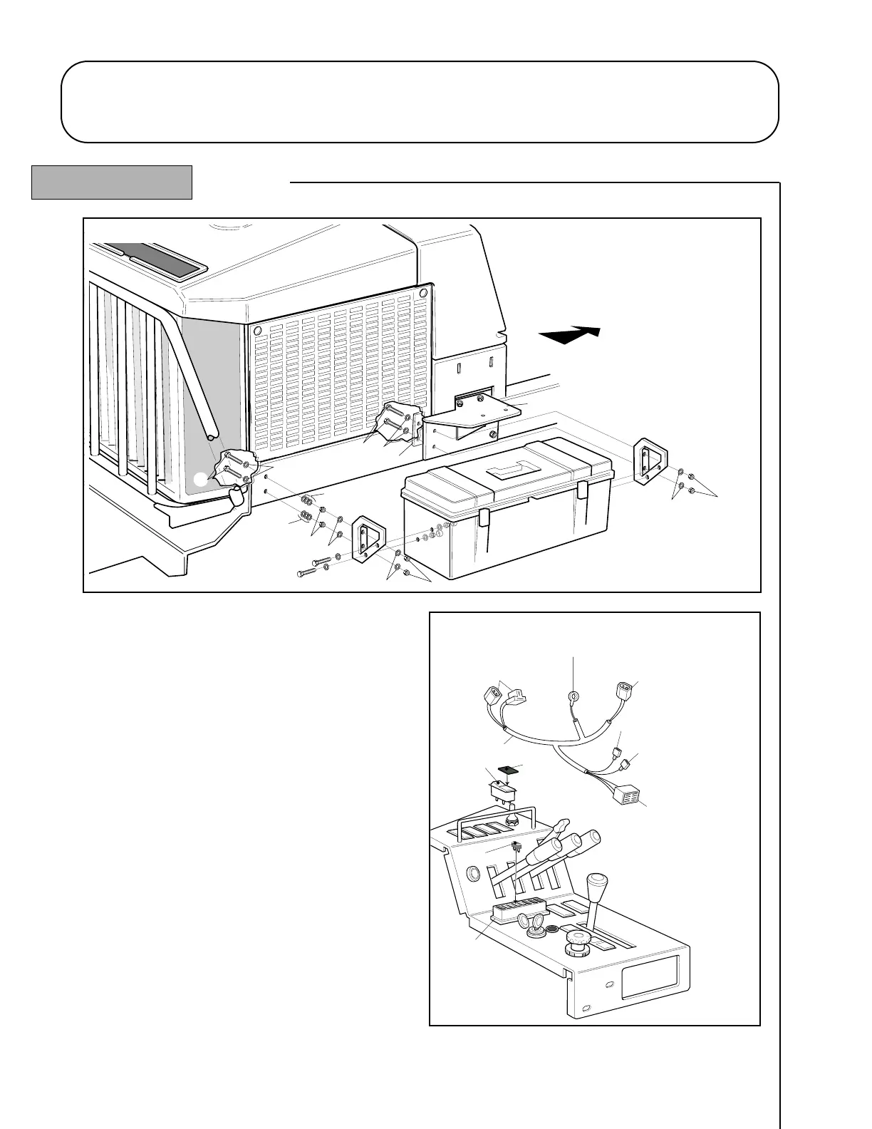
15. Thread connectors ‘A’ and ‘B’ under the R.H. fuel tank
support forward of the cab support bracket.
16. Route the harness across the chassis and thread
connector ‘D’ under the L.H. fuel tank support forward
of the cab support bracket.
17. Route ring terminal ‘C’ to the earth connection point
located beneath the L.H. side of the chassis and connect.
18. Route the remaining arm of harness to the control panel.
19. Connect the wiper / washer terminal (red/blue) to the
fuse box. Refer - figs. 5 and 5
A.
20. If a beacon is fitted (optional kit), connect the beacon
terminal (orange) to the beacon switch on the control panel.
21. Remove the wiper/washer switch position blanking
cover in the control panel and pass the 8-way connector
‘G’ through the aperture from the underside. Fit the lens
(item 54) to the rocker switch (item 53) and assemble to
the 8-way connector. Snap the switch into the control panel. Refer - figs. 5 and 5
A.
22. Secure the wiring harness in position with the cable ties (items 57) supplied.
23. Fit the 5 amp fuse (item 56) into the fuse box. Refer - figs. 5 and 5A.
1.16 1.16
CAB GENERAL ASSEMBLY
R.H. Inside Rear Corner
L.H. Inside Rear Corner
(Located beneath L.H. side of chassis)