Continued.
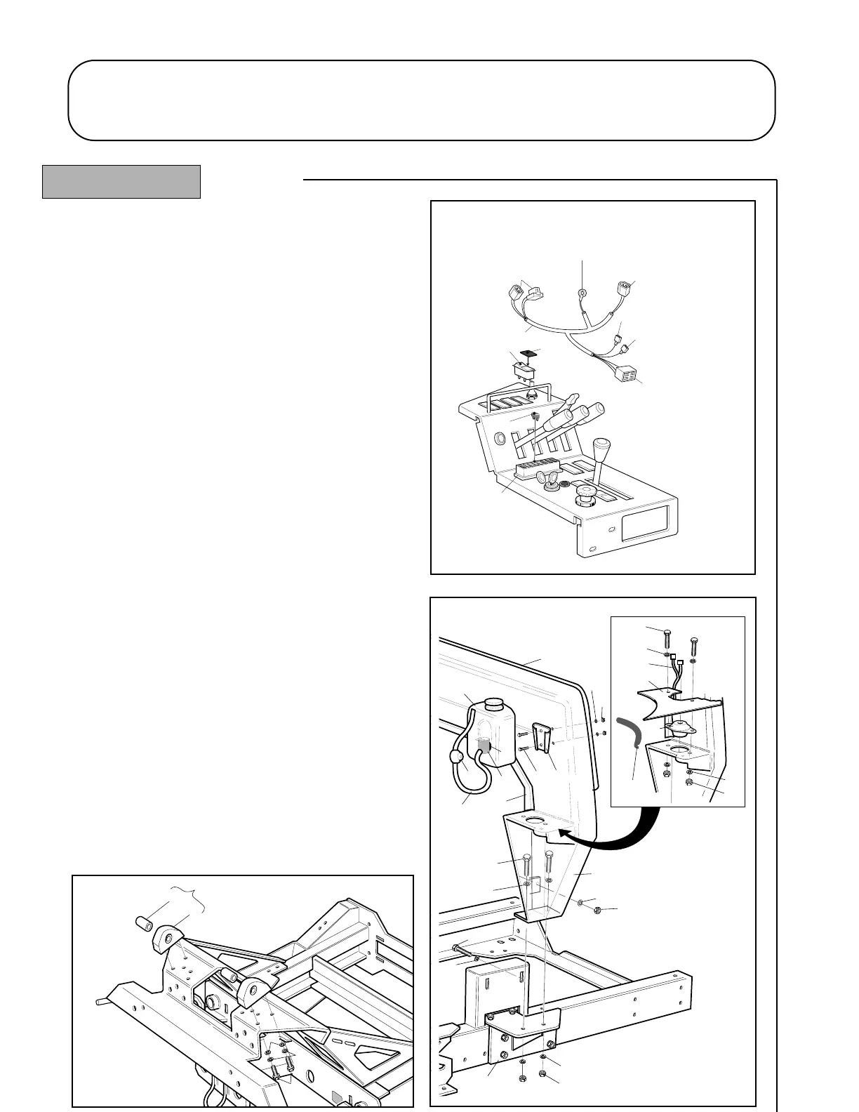
24. Fit the draught excluder and protection strip (items
33, 34) to the rear cab mount (item 32). Fit the
washer bottle bracket (item 46) with fasteners (items
47, 48, 49). Refer - fig. 6.
25. Fit the rear cab mount assembly (item 32) over the
fuel tank and locate onto the R.H. and L.H. cab
support brackets. Secure using fasteners (items 16,
17, 19) but do not tighten at this stage.
26. Fit the edging strip (item 40) to the cab infill plates
(items 39) and assemble these together with the
isolator mounts (items 35) to the rear cab mount
assembly with fasteners (items 37, 13, 14). Tighten
until the infill plates just move. Refer - fig. 6.
27. Route the wiring harness leads on each side of the
machine up in front of the rear cab mount assembly
and through the slots in the cab infill plates.
28. Lower the platform.
29. Secure the pivot block and mount assemblies (items
7) to the chassis with M12 fasteners (items 16, 17,
18) and torque to 75Nm. Refer - fig 7.
1.17 1.17
CAB GENERAL ASSEMBLY
ASSEMBLY
R.H. Inside Rear Corner
L.H. Inside Rear Corner
(Located beneath L.H. side of chassis)
 Loading...