9
ME 30
2 Electrical Connection
2.1 Transducer Connection
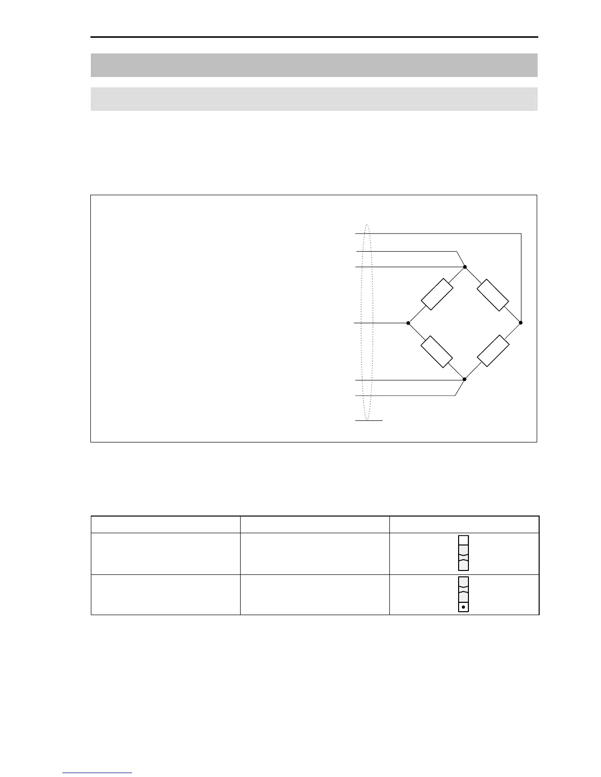
Strain gauge transducers are connected by means of 6-wire circuits.
With transducers in 4-wire technology the sensing leads are not needed. In
this case the contacts 32a+c and 28a+c on the connector must be linked.
screen pins 31a+c. . . . . . . . . . . . . . . . . .
rd
gy
bk
wh
bu
gn
ye
measuring signal (–) pin 30a. . . . . .
sensing line to 32a (–) pin 32c. . . . .
bridge supply voltage (–) pin 32a. .
measuring signal (+) pin 30c. . . . . .
bridge supply voltage (+) pin 28a. .
sensing line to 28c (+) pin 28c. . . . .
contact
(alternatively 29a+c)
Fig. 2.1: Bridge connection
The required bridge excitation voltage set by the factory is 5V(symmetrical
about ground). It can be switched to 2.5V by switch S25.
U
B
Bridge resistance Switch S25
2.5V R
B
≥60...4000Ω
5V
(ex-works settings)
R
B
≥110...4000Ω
The safety barriers SD01 must be wired into the connecting lines (see chap-
ter 5.4) for transducers in EEx(i) design.
 Loading...