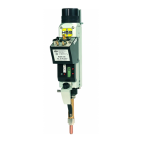
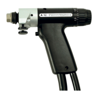
The HBS KAH 412 is an automatic stud welding head designed for CD (Capacitor Discharge) or ARC (Arc Stud Welding) stud welding processes. It is intended for use with standardized stud welding elements, ensuring that the strength of the welded joint is not diminished. This welding head must only be connected to HBS stud welding units.
Function Description:
The KAH 412 welding head is a precision tool for automated stud welding. It integrates several components to facilitate accurate and repeatable welding operations. The main assemblies include a rear cap, spring adjustment screw, display spring adjustment, lift adjustment screw, connection casing, display lift, screw height adjustment, and height adjustment.
The device operates by moving a welding element into the chuck, which is then positioned relative to the workpiece. The Z-axis (in setup mode) is used for working position, and a contact signal is displayed on the stud welding unit. For automatic operation, the insertion depth of the pneumatic working stroke is manually set, and the locking screw for height adjustment is loosened. The height adjustment (protrusion depth) is then set according to the welding task. The Z-axis can also be moved to the home position. On CNC systems, the protrusion is controlled via the CNC program.
The KAH 412 supports various stud welding processes, including capacitor discharge (gap welding), drawn arc (short-cycle stud welding), and drawn-arc welding with shielding gas. The selection of the appropriate process depends on the stud diameter, welding process used, and the shape of the spatter ring or welding seam.
Important Technical Specifications:
- Welding Range: M3 to M8, dia. 3 to 8 mm (dia. 10/12/12.7 mm with modification only)
- Stud Length: 8 to 40 mm (standard - other lengths on request)
- Stud Material: Mild steel, stainless steel, aluminum, brass
- Lift: Adjustment range 5 mm, arresting
- Spring Force: Arresting
- IP Code: IP 20 (protect against humidity)
- Workplace Noise Level: > 90 dB (A) may occur during welding
- Ambient Temperature Limits: 0 °C to 40 °C
- Dimension (L x W x H): 375 x 86 x 145 mm (with chuck and quick change system)
- Weight: 3.4 kg
- Order No.: 94-31-412C
Dimensional Drawing (Welding Head KAH 412):
- Length: 400 mm
- Width: 143 mm
- Height: 130 mm (from base to top of DIN74-Km6 connection)
- DIN74-Km6 (4x) connection
- WAF17 (wrench size) for certain adjustments
- Various diameters: 23 mm, 32 mm, 38 mm, 40 mm, 45 mm, 50 mm, 58 mm, 66 mm, 20 mm, 27 mm.
Downholder Pneumatic (Order No. 80-08-702):
- Length: 451 mm (extended 551 mm)
- Width: 100 mm
- Stroke: 100 mm
- Inside diameter: 40 mm
- Various dimensions: 10 mm, 29 mm, 43.5 mm, 57 mm, 60 mm, 85 mm, 189 mm, 212 mm.
Usage Features:
- Adjusting the Working Position: The welding head allows for precise adjustment of the working position. This involves setting the rear cap, spring adjustment screw, pressure spring, pointer, cylindrical pin, and lift adjustment screw.
- Protrusion Determination: The protrusion for PT, UT, IT, PS, US, IS type studs should be about 1.5 mm for capacitor discharge. For contact welding tip ignition, the protrusion of the welding element should be one level shorter than standard (e.g., length of the welding element 12 > pin stop 10). For drawn arc welding, the protrusion varies based on stud diameter (e.g., 5 mm stud has 2.5 mm protrusion, 12 mm stud has 4.4 mm protrusion).
- Equipping the Welding Head: The welding head is equipped with various components, including chuck, retaining nut, guide bushing, pin stop, plunger, slot piston, support for feed tube, trigger pin complete, feed tube, pin 2 mm, and socket wrench WAF 17.
- Adjusting Welding Parameters: Lift and spring force are dependent on the workpiece and welding elements. The manual provides detailed tables for selecting applicable parameters based on stud welding units, material of welding elements, and welding process (CDMI 2402, SCD 3201, ARC 800, IT 50 / IT 90 / IT 1002).
- Switching off the Battery: The effective service life of the battery can be extended by switching off the battery indicator after the welding head has been prepared. This is done by pushing the trigger for "0 / ON" next to the display for approximately 2 seconds. The display goes out briefly, then changes to "OFF" before switching off again.
Maintenance Features:
- Cleaning: The casing of the welding head should be cleaned with a slightly damp cloth if necessary. Solvents, compressed air, or flying dust particles should not be used.
- Inspection and Tests: Regular inspection of the chuck for burning marks, bellows for proper assembly, and type plates for legibility and damage is required.
- Removing Equipment: The welding head can be moved to a suitable working position for removing components like the retaining nut, chuck, guide sleeve, and pin stop.
- Disassembly: The welding head can be removed from the CNC system by disconnecting all connections and loosening the screw for the dovetail mount.
- Changing the Battery: The welding head uses a CR 2032 3 volt battery. The operating life is about two years. The battery indicator "B" on the display illuminates when the battery is low. The battery can be changed by removing four screws, the connection casing, the cylinder head bolt, and the double-sided adhesive pad.
- Storage: The welding head should be stored in a safe and dust-free location, protected from moisture and metallic contamination. Storage temperature should be -5 °C to +50 °C, with relative humidity of 0 % - 50 % at +40 °C and 0 % - 90 % at +20 °C.
- Disposal: The welding head should be disposed of via the manufacturer or a specialist disposal company, not in domestic refuse.
Safety Precautions:
The manual emphasizes important safety precautions, including:
- Danger from incorrect use: Use the stud welding machine only for the purpose described in this manual.
- Danger for unauthorised operating personnel: Work with the stud welding machine only when appropriately trained, instructed, and having read and understood the operating manual.
- Danger from unauthorised modifications: Never modify the stud welding machine or parts thereof without obtaining a clearance certificate from the manufacturer.
- Life-threatening danger for wearers of active implanted cardiac devices: Persons with active implanted medical devices, passive implanted medical devices, or pregnant workers should not operate the stud welding machine if they are among the group of workers at particular risk within the meaning of the EMF directive.
- Danger from fumes and airborne particulates: Switch on the welding fume extractor at the place of work. Ensure that the room is well ventilated and never weld in rooms with a ceiling height of less than 3 m.
- Danger from glowing metal spatter (fire hazard): Wear proper protective clothing (gloves, apron, full-ear hearing protection, safety helmet, safety shoes, safety goggles). Ensure an approved fire extinguisher is available. Do not weld when wearing working clothes soiled with flammable substances.
- Safety notices in accordance with EMF directive 2013/35/EU: Lay all cables as close together as possible. For proper bundling and safeguarding of the cables, HBS offers protective tubes. Do not position yourself between the welding cables. Only lay the cables to one side and position them as far as possible from the operating personnel. Do not loop the cables over your body. Use the shortest possible welding cables. Place portable welding power sources as far away as possible while welding. If possible, do not operate welding power sources in the immediate vicinity of other persons.
Symbols and Terms Used:
- Danger: Warns of hazards that can lead to injury of persons or to considerable material damage.
- Caution: Problems in operating may occur if this information is not observed.
- No access for people with active implanted cardiac devices.
- No access for persons with implants made of metal.
- No access for pregnant women.
- Danger (electrical hazards): Warns of electrical hazards.
- Danger (electromagnetic fields): Warns of electromagnetic fields that can be generated during welding.
- Personal protective clothing: These symbols prompt you to wear personal protective clothing when working with the stud welding unit.
- Ear protection: This symbol prompts you to wear ear protection. A loud bang > 90 dB (A) can occur during the welding process.
- Tip: Cross-reference to useful information on the use of the stud welding machine.
- Cross-references: Cross-references in this operating manual are marked with this symbol or are printed in italics.
- Fire hazard: Have a suitable fire extinguisher for the working area ready before starting work.
- Work instruction:
- List:
The manual provides a comprehensive troubleshooting guide for various faults, including welding elements not firmly attached, scorching at the welded element, automatic welding head does not weld, and trigger defective. It also includes a detailed maintenance schedule for power and control cable connections, chuck, guide sleeve, plunger, feed tube, pin stop, and feeding tube, specifying daily, weekly, every two months, and every six months checks and tasks.