HBX CPU-1000 HVAC Controller
Version 1.38
© HBX Control Systems Inc. 2012
Introduction 5 /6 Page 5
4. Serial Number and Bar Code:
This label will identify the entire factory ordered options
and the date of manufacture. It can also be used for re-
ordering and will be required in the event of factory
service assistance or warranty claim.
5. Communication Connection:
The standard communications port (RS-232) is found
immediately below the bar code label. Optional
communications software needs to be purchased to
enable a connection. Please consult factory or dealer.
Only a CAB-0100 can be inserted into this
connection without causing damage.
6. 120 VAC Pump Outputs:
There are three separate (3-wire) 120VAC output power
terminals designed to run either a pump or fan.
7. 120 VAC Power Input:
There is one (3-wire) terminal block for incoming
120VAC power.
8. Miscellaneous Relays:
There are two (2-wire) miscellaneous/auxiliary relay
terminal blocks. These can be used to wire a variety of
miscellaneous devices up to 10Amps.
9. Thermistor/Sensor Inputs:
There are three (2-wire) sensor/thermistor inputs.
Under no circumstance should power be
applied to these terminals! Permanent damage
to the Controller’s circuitry may result.
10. Demand Inputs:
There are three (2-wire) “demand” control inputs.
Control signals between 20-240VAC are designed to
trigger a variety of commands within the Controller, for
example run a heat demand, a setpoint demand and/or
a DHW demand.
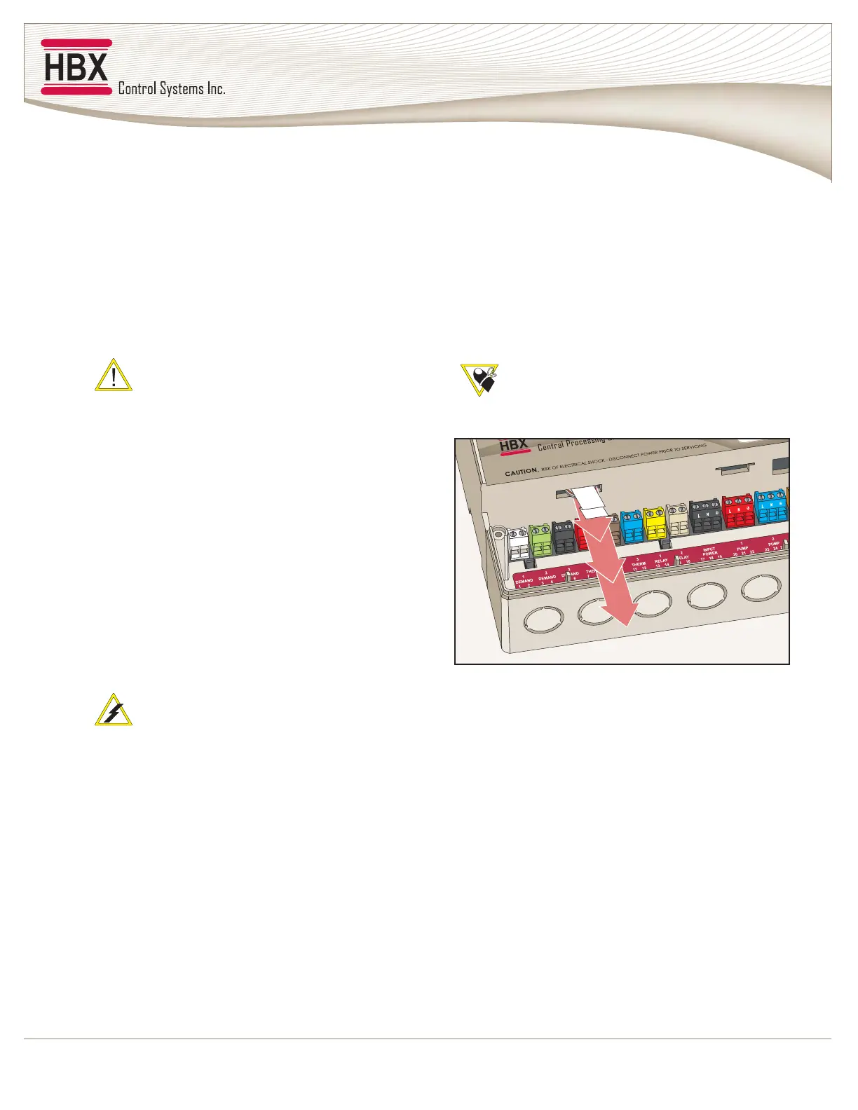
11. Backup Battery:
The lithium-ion battery is purely a back-up supply for
the real time clock and will keep the clock refreshed
during a power interruption to the Control.
Prior to installation, please remove the
protective paper strip to activate the back-up
battery as shown below.