HBX CPU-1000 HVAC Controller
Version 1.38
Introduction 6/6 Page 6
21
SD
1
SD
1
43
SD
2
SD
2
65
SD
3
SD
3
RG
021
82
N
L
7262
RG
021
52
N
L
4232
RG
021
22
N
L
1202
RG
021
91
N
L
8171
LR
2
LR
6151
2
LR
1
LR
4131
1
MT
3
MT
2111
3
MT
2
MT
019
2
MT
1
MT
87
1
v 042-02 v 042-02 v 042-02
EREH REWOP TCENNOC TON OD
A 01
A 01
A 01
A 01A 01
0001 UPC
XBH
TINU GNISSECORP LARTNEC
yaleR 3P
yaleR 2P
yaleR 1P
CAV 021 rewoP ylppuS
2 yaleR :csiM
1 yaleR :csiM
1 langiS dnameD
2 langiS dnameD
3
langiS dnameD
1 rotsimrehT
2 rotsimrehT
3 rotsimrehT
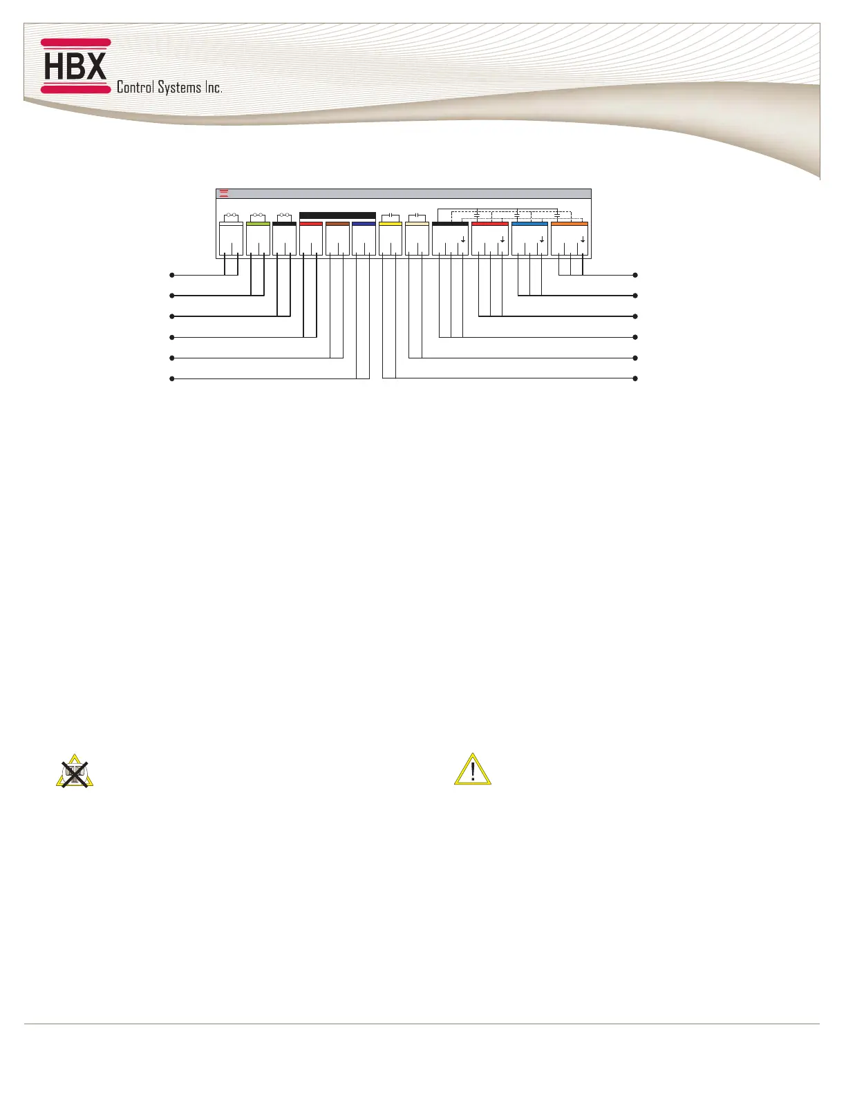
0001 UPC XBH rof snoitangiseD lanimreT
Demand Signal 1 - Any heat demand signal powered by 20 -
240VAC. E.g. 24VAC Thermostat. This trigger will follow the
Outdoor Reset Curve calculated by the Control.
Demand Signal 2 - Any heat demand signal powered by 20 -
240VAC. E.g. 24VAC Thermostat. This trigger will not follow the
Outdoor Reset Curve but stage the boiler to its maximum boiler
temp programmed in the Control. Demand 2 has an alternative
function and can be programmed to be the default input for a flow
proof switch (only available with applications using pump
sequencing).
Demand Signal 3 - Any heat demand signal powered by 20 -
240VAC. E.g. 24VAC Thermostat/Aquastat. This trigger is
designed to stage the boiler temp to satisfy the DHW settings
programmed in the Control.
Thermistor 1 - Boiler Sensor
Thermistor 2 - System Sensor (alternative position for DHW
Sensor, Staging/DHW Systems only)
Thermistor 3 - Outdoor Sensor
TM1, TM2 & TM3 are designed for 10K Ohm
Thermistors and must never be subjected to any
external power supply (voltage or current)
P3 Relay - Any pump (or fan) output rated to a max of 10Amps
120VAC. This relay is pre-programmed to be the default DHW
pump supplying a DHW in-direct hot water tank. Its alternative
function is to be an Injection Pump relay when PMIp is the
injection mixing strategy.
P2 Relay - Any pump (or fan) output rated to a max of 10Amps
120VAC. This relay is pre-programmed to be the default (low
temp) system pump. When programmed for a mixing system.
P1 Relay - Any pump (or fan) output rated to a max of 10Amps
120VAC. This relay is pre-programmed to be the default boiler or
(High Temp) system pump.
P1 & P2 - The (2) dedicated relays when pump sequencing is
selected in the Controls program. P1 & P2 become the Hi Temp
system pumps in a commercial application requiring pump
sequencing.
Supply Power - The 3-wire 120VAC input to the control.
Protected by a 30Amp breaker or fuse.
Misc: Relay 2 - This relay is the default relay for bringing on the
2nd Boiler or Boiler stage. It has an alternative function and can
be used as an injection valve. This may be PMIv for radiant
mixing or a on/off valve for DHW indirect storage tanks.
Misc Relay 1 - This relay is the default relay for bringing on the
1st Boiler or Boiler stage.
Misc Relays 1&2 are Dry Contacts and rated for
a max of 10Amps