HBX CPU-1000 HVAC Controller
Version 1.38
Page 8
Centr a l Proces s i n g U n i t
CPU-1000
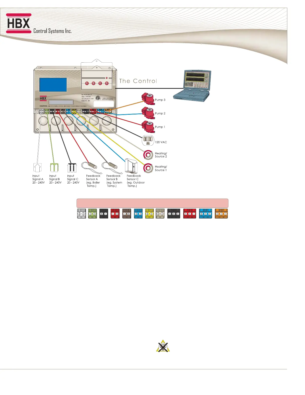
WIRING OPTIONS
White Green Black Red Brown Blue Yellow Natural Black Red Blue Orange
DEMAND DEMAND DEMAND THERM THERM THERM RELAY RELAY PUMPPUMPPUMP
INPUT
POWER
1
13579111315246810121416 26232017 27242118 28252219
1122212333
White (1-2) Demand 1, 2-wire control input
20-240VAC
Green (3-4) Demand 2, 2-wire control input
20-240VAC
Black (5-6) Demand 3, 2-wire control input
20-240VAC
Red (7-8) Therm 1, 2-wire thermistor
Eg. boiler sensor
Brown (9-10) Therm 2, 2-wire thermistor
Eg. system sensor
Blue (11-12) Therm 3, 2-wire thermistor
Eg. outdoor sensor
Yellow (13-14) Relay 1, misc. auxiliary
10Amps
Natural (15-16) Relay 2, misc. auxiliary 10Amps.
Also becomes the default terminals
when selecting PMIv (valve injection).
Explained further on page 63.
Black (17-19) Input Power, 3-wire.
This is the main input power supply
connection. 17 is line, 18 is neutral and
19 is earth ground.
Red (20-22) Pump 1, 3-wire 120VAC output power
to pump or fan number 1. 20 is line, 21
is neutral and 22 is earth ground.
Blue (23-25) Pump 2, 3-wire 120VAC output
power to pump or fan number 2. 23 is
line, 24 is neutral and 25 is earth ground.
Orange (26-28) Pump 3, 3-wire 120VAC output power
to pump or fan number 3. 26 is line, 27
is neutral and 28 is earth ground. Also
becomes the default terminal when
using PMIp (pump injection).
Explained further in the manual.
Terminals 7-12 must not be subjected to any
external power source