HBX CPU-1000 HVAC Controller
Version 1.38
Introduction 4/6 Page 4
Example:
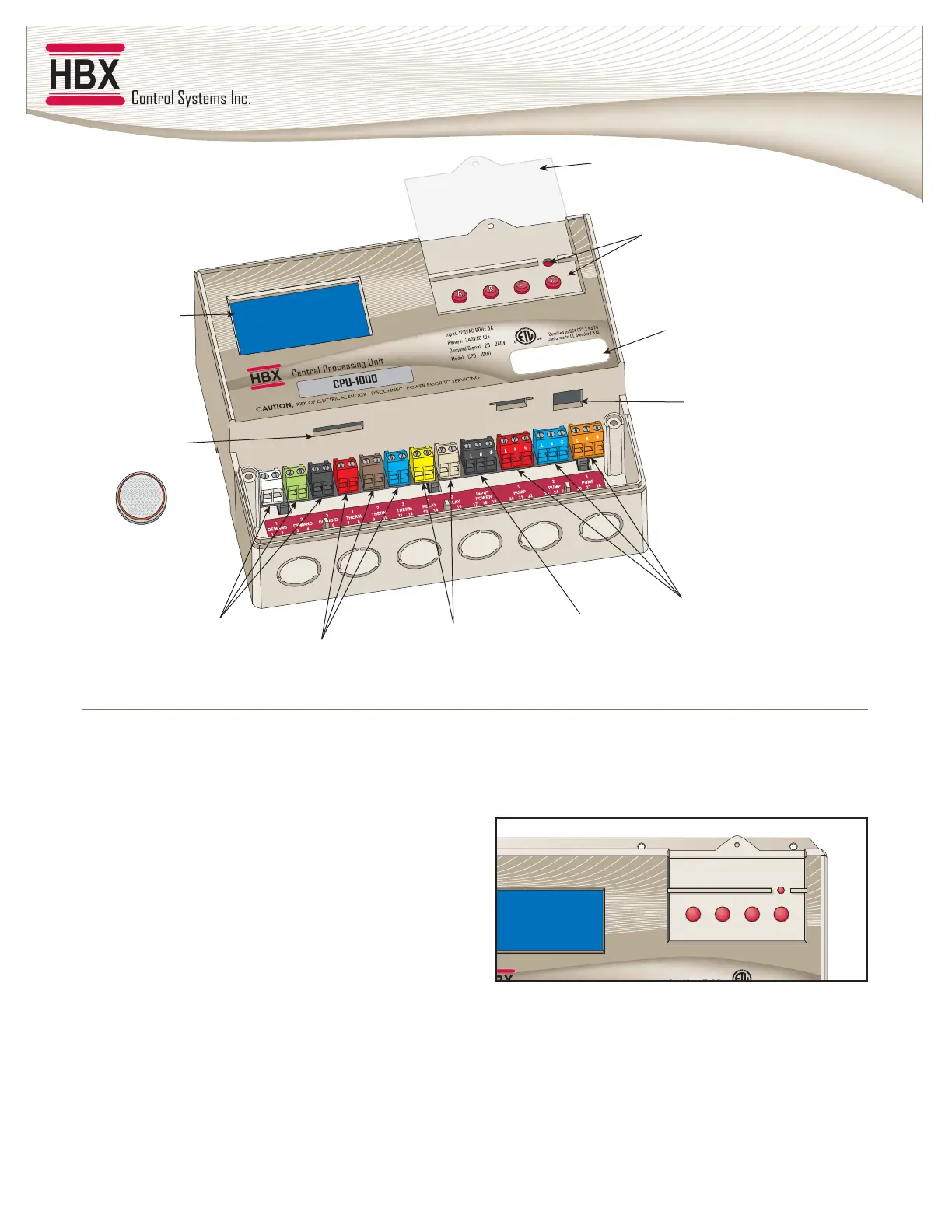
Viewing from top left and moving right in a clockwise
direction:
1. Back-Lit Graphic Display:
The display is one of the key features of the Controller.
Depending upon which mode of operation is selected,
you will be able to view most common system values
simultaneously. It will also serve as a visual indicator
when in the programming mode.
2. Lockable Keypad Cover:
Once your system has been programmed and optimized
there should be little or no reason for further changes.
The Controller has been designed with the ability to
physically “hard-lock” the keypad to prevent tampering
with the settings.
3. Menu and Programming Buttons:
These buttons will be used to set up the Controller
during commissioning and for toggling between
displays or troubleshooting at a later date if necessary.
A. Moves screen or value down
B. Moves screen or value up
C. Enters a value, parameter, or setting, toggles Y/N
D. Return to last screen and access programming mode
• Reset- Protected from being accidentally pushed
2. Lockable
Keypad Cover
3. Menu / Reset /
Programming
Buttons
4. Serial Number /
Bar Code Tracking
5. Communication
Connection
6. 120 VAC
Pump Outputs
7. 120 VAC
Power Inputs
8. Miscellaneous
Relays
9. Thermistor /
Sensor Inputs
10. Demand
Inputs
11. Backup
Battery
1. Graphic
Display
MAIN PARTS AND LABELS
A
B
C
D
Input: 120VAC 60Hz 5A
Relays: 240VAC 10A
DdSl20 240V
Certified to CSA C22 2 No 24
1000