Do you have a question about the Heat Controller B-DVH12SD-0 and is the answer not in the manual?
General safety instructions to prevent injury and property damage during installation and operation.
Warnings related to installation, operation, and product handling.
Lists model numbers for indoor and outdoor units based on capacity.
Specifies minimum clearances required around indoor and outdoor units.
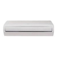
Details the various features and functions of the mini-split system.
Provides physical dimensions (width, depth, height) for the indoor unit.
Shows dimensions and hole specifications for the indoor unit mounting bracket.
Provides physical dimensions for the outdoor unit.
Diagram illustrating the refrigerant flow for cooling-only (DVC) models.
Diagram showing the refrigerant cycle for heat pump (DVH) models.
Electrical schematics for the indoor unit's internal wiring and connections.
Electrical schematics detailing the wiring of the outdoor unit.
Guidelines for electrical wiring, including code compliance.
Specifies gas and liquid line set connection diameters.
Maximum allowable lengths and elevation differences for line sets.
Instructions for adding refrigerant based on line set length.
Defines acceptable temperature and humidity ranges for Cool, Heat, and Dry modes.
Identifies sensor abbreviations and explains indoor display icons.
Details critical protection mechanisms for compressor, fan, and inverter module.
Describes unit operation in fan-only mode.
Explains compressor and fan operation based on temperatures.
Details compressor frequency control based on outdoor temperature in heating.
Defines outdoor fan speed based on ambient temperature in heating mode.
Explains indoor fan speed control based on coil temperature in heating.
Specifies conditions that trigger defrost mode.
Criteria for ending the defrost cycle.
Fan speed and louver behavior in dry mode.
Compressor frequency reduction based on temperature difference in dry mode.
Lists indoor unit error codes and their malfunctions.
Explanation of status and error indications from LEDs on the outdoor PCB.
Details how LED3 (Red) and LED4 (Green) correspond to specific indoor unit error codes.
Diagnosis and solution for EEPROM parameter errors.
Troubleshooting steps for communication errors.
Diagnosis and solution for zero crossing signal errors.
Troubleshooting for indoor fan speed control issues.
Diagnosis and solution for temperature sensor errors.
Troubleshooting for refrigerant leakage detection errors.
Diagnosis and solution for IPM malfunction or over-current errors.
Troubleshooting for compressor top temperature protection errors.
Diagnosis and solution for inverter compressor drive errors.
Service port pressures for cooling mode at various temperatures.
Service port pressures for heating mode at various temperatures.
| Brand | Heat Controller |
|---|---|
| Model | B-DVH12SD-0 |
| Category | Heat Pump |
| Language | English |