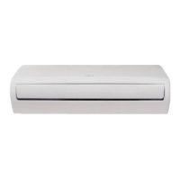
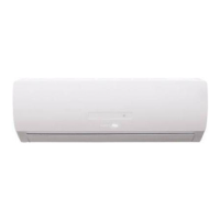
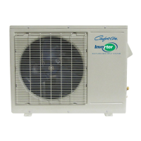
Do you have a question about the Heat Controller B-DVC24SD-1 and is the answer not in the manual?
Essential safety guidelines for installation, operation, and maintenance.
Details on unit components, model numbers, clearances, and key features.
Specifications for indoor and outdoor unit physical dimensions and mounting.
Visual representation of refrigerant flow for cooling and heat pump models.
Electrical schematics for indoor and outdoor unit connections.
Guidelines for electrical setup, line set connections, lengths, and field charging.
Recommended temperature and humidity ranges for optimal unit performance.
Explanation of display icons, abbreviations, and system protection mechanisms.
Descriptions of various operational modes like Cooling, Heating, Dry, Sleep, and Timer.
List and explanation of error codes displayed by the indoor unit.
Common errors and diagnostic procedures for the outdoor unit.
Troubleshooting steps for EEPROM parameter errors in indoor/outdoor units.
Steps to diagnose and resolve communication errors between indoor and outdoor units.
Procedure for troubleshooting zero crossing detection errors.
Steps to diagnose issues with indoor fan speed control.
Procedures for diagnosing open or short circuits in temperature sensors.
Steps to identify and resolve refrigerant leakage detection errors.
Troubleshooting for IPM malfunctions and IGBT over-current protection.
Diagnosis for high temperature protection of the compressor top.
Steps to diagnose inverter compressor drive errors.
Table of expected pressure values for cooling and heating modes.
| Cooling Capacity (BTU) | 24000 |
|---|---|
| HSPF | 10 |
| Voltage | 208-230V |
| Phase | 1 |
| Power Supply | 60Hz |
| Refrigerant | R410A |
| Operating Temperature (Heating) | -5°F to 75°F |
| Indoor Unit Noise Level | 42 dB(A) |
| Outdoor Unit Noise Level | 55 dB(A) |
| Heating Capacity (BTU) | 24000 |


