InstallationInstructions15
059840‐00Rev.AHeat‐TimerCorp.
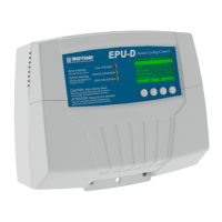
3. PositiontheEnclosurebaseinthedesiredlocation,andthensecurethebaseinplaceusingfourscrews
(provided)throughthemountingholes(1)onthebackoftheEnclosurebase.
Figure5: EPU‐DEnclosureBase
MountingtheDisplayModule
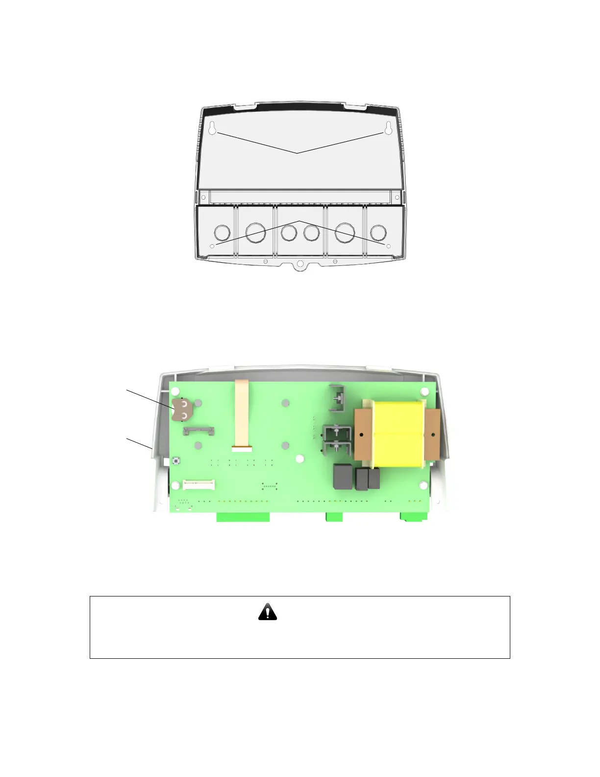
1. TurntheEPU‐Ddisplaymodule(1)overtorevealthebattery(2).Removetheplastictabtoactivatethe
battery.
Figure6: EPU‐DDisplayModuleBatteryLocation
NOTE:Thebatteryisacoinlithiumbattery(CR2032‐HeatTimerp/n020002‐00)thatisusedtomaintain
thecontrol’sdateandtimeduringpoweroutages.Thebatterycanmaintaintheclockforuptoatotalof
100days.
2. PositiontheDisplayModuleintothebaseandsecureitinplaceusingthemiddlescrewsremovedinStep 2
above.
NOTE:DonotreplacetheEnclosureWiringCoveruntilallwiringiscompleted.
3. Continuewith“WiringtheEPU‐D”onpage 16.
CAUTION
Donotactivatethebatteryunlessyouplantokeepthecontrolcontinuously
powered.Ifthecontrolhasnopower,thebatterywillloseitschargein100days.