InstallationInstructions19
059840‐00Rev.AHeat‐TimerCorp.
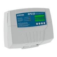
WiringtheOutdoorTemperatureSensor
NOTES:
• UseonlytheprovidedHeat‐Timertemperaturesensor(p/n904220‐00).
• Foracceptablesensorlocations,see“OutdoorTemperatureSensor”onpage 8.
1. RuntheOutdoorTemperatureSensorwiresthroughaknockoutlocatedonthebottomof
theEPU‐Denclosure.
NOTE:Thesensorwirescanbeextendedupto500feet(152.5meters)usingan18AWG
shielded2‐conductorcable(Heat‐Timerp/n703001‐01orequivalent#18/2cable).
2. ConnecttheOutdoorTemperatureSensorwirestoterminals11and12ontheEPU‐D.
3. Connecttheshieldtoterminal12ontheEPU‐D.
NOTE:Donotconnecttheshieldatthesensorend.
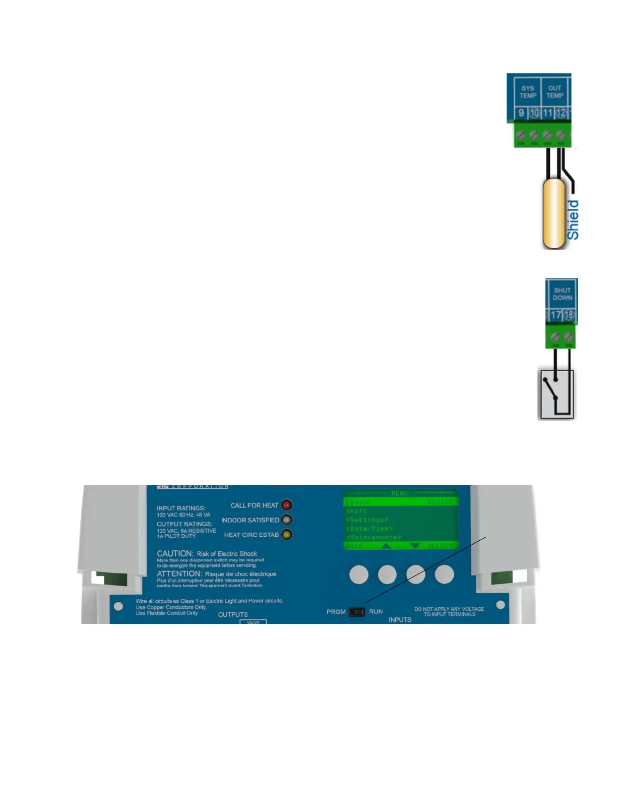
WiringtheOptionalRemoteShutdown/TSTAT
1. RuntheRemoteShutdownwiresthroughaknockoutlocatedonthebottomoftheEPU‐D
enclosure.
2. ConnecttheRemoteShutdowndry‐contactwirestoterminals17and18ontheEPU‐D.
NOTE:Theterminalscanbeconfiguredasnormally‐openornormally‐closed.Ifconnectedto
aremoteshutdown,theterminalsneedan“open”signal.IfconnectedtoaTSTAT,the
terminalsneeda“closed”(short)signal.
Powering‐OntheEPU‐D
1. ApplypowertotheEPU‐D.
2. PlacethePRGM/RUNswitch(1)ontheEPU‐DinthePRGMposition.
3. PerforminitialprogrammingoftheEPU‐D(see“InitialProgrammingoftheEPU‐D”onpage 20).
CompletingtheInstallation
AftertheEPU‐Dispowered‐onandtheinitialprogrammingiscomplete:
1. PlacethePRGM/RUNswitch(1)ontheEPU‐DintheRUNposition.
2. ReplacetheEPU‐Denclosurewiringcoverandsecureitinplacewithtwoscrews.
3. Optionallysecuretheenclosureusingapadlockwithamaximumshankdiameterof⅛".