18EPU‐DInstallationandOperationManual
059840‐00Rev.A Heat‐TimerCorp.
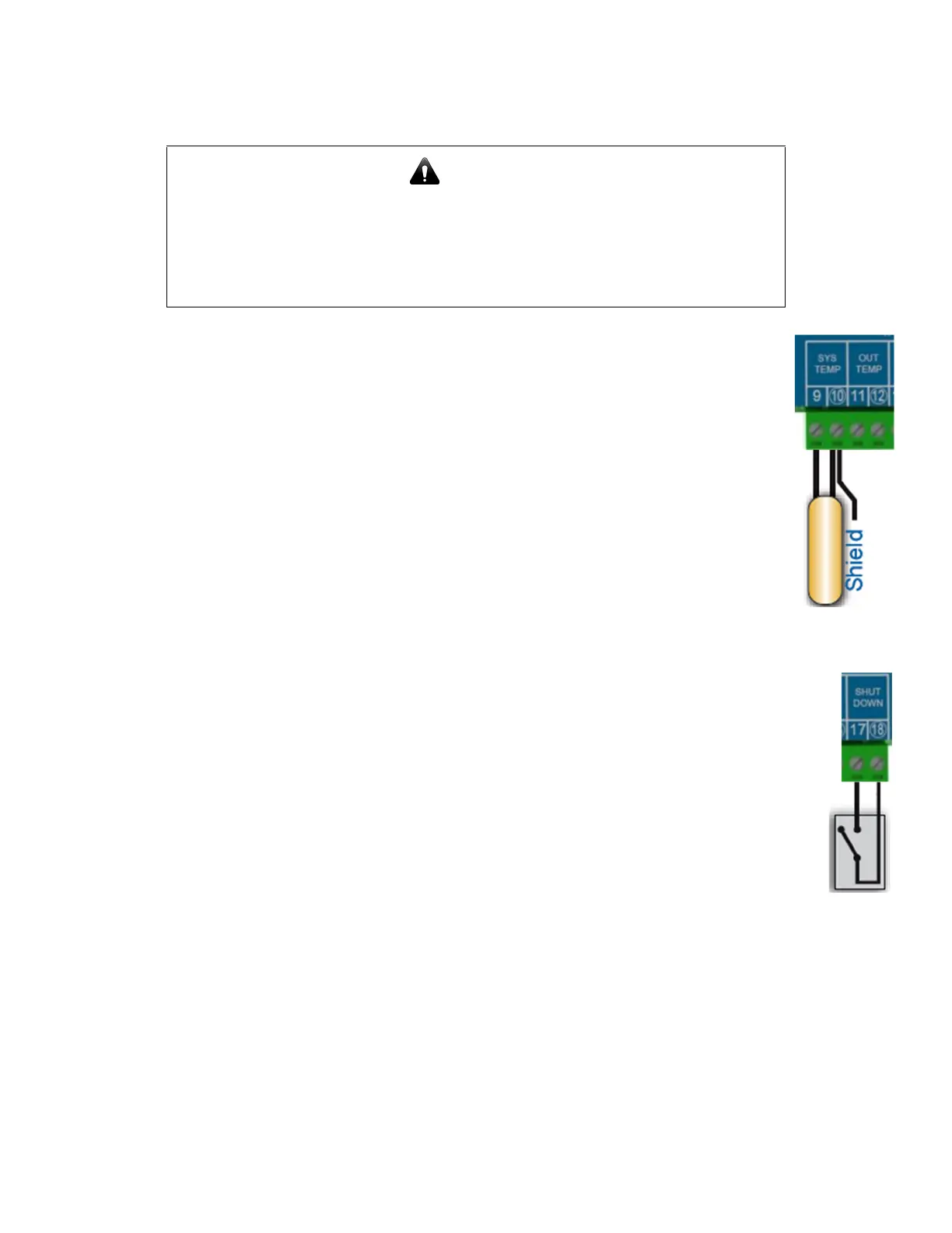
InputWiring
WiringtheHeatingSystemSensor
NOTES:
• UseonlytheprovidedHeat‐Timerheatingsystemsensor(p/n904220‐00).Seepage 8fora
descriptionofthesensor.
• Foracceptablesensorlocations,see“PipingDiagrams”onpage 38.
1. RuntheSystemTemperatureSensorwiresthroughaknockoutlocatedonthebottomof
theEPU‐Denclosure.
NOTE:Thesensorwirescanbeextendedupto500feet(152.5meters)usingan18AWG
shielded2‐conductorcable(Heat‐Timerp/n703001‐01orequivalent#18/2cable).
2. ConnecttheSystemTemperatureSensorwirestoterminals9and10ontheEPU‐D.
3. Connecttheshieldtoterminal10ontheEPU‐D.
NOTE:Donotconnecttheshieldatthesensorend.
WiringanOptionalPressuretrolSensor
NOTES:
• Heat‐TimerdoesnotprovideaPressuretrolsensor.
• TheoptionalPressuretrolsensormustbeareverse‐actingsensor.Seepage 8foradescriptionof
thesensor.
• Foracceptablesensorlocations,see“PipingDiagrams”onpage 38.
1. ConnectwirestothePressuretrolnormally‐closedterminals.
2. RunthewiresfromthePressuretrolthroughaknockoutlocatedonthebottomoftheEPU‐D
enclosure.
NOTE:Thesensorwirescanbeextendedupto500feet(152.5meters)usingan18AWGshielded
2‐conductorcable(Heat‐Timerp/n703001‐01orequivalent#18/2cable).
3. ConnectthePressuretrolwirestoterminals9and10ontheEPU‐D.
4. Connecttheshieldtoterminal10ontheEPU‐D.
NOTE:Donotconnecttheshieldatthesensorend.
CAUTION
ToavoiddamagetotheEPU‐D,NOVOLTAGEcanbeappliedtotheEPU‐Dinput
terminals.
Class2voltagewiring(low‐voltagesensorandcommunicationwires)mustuse
adifferentenclosureknockoutandconduitthananyClass1voltagewiring.