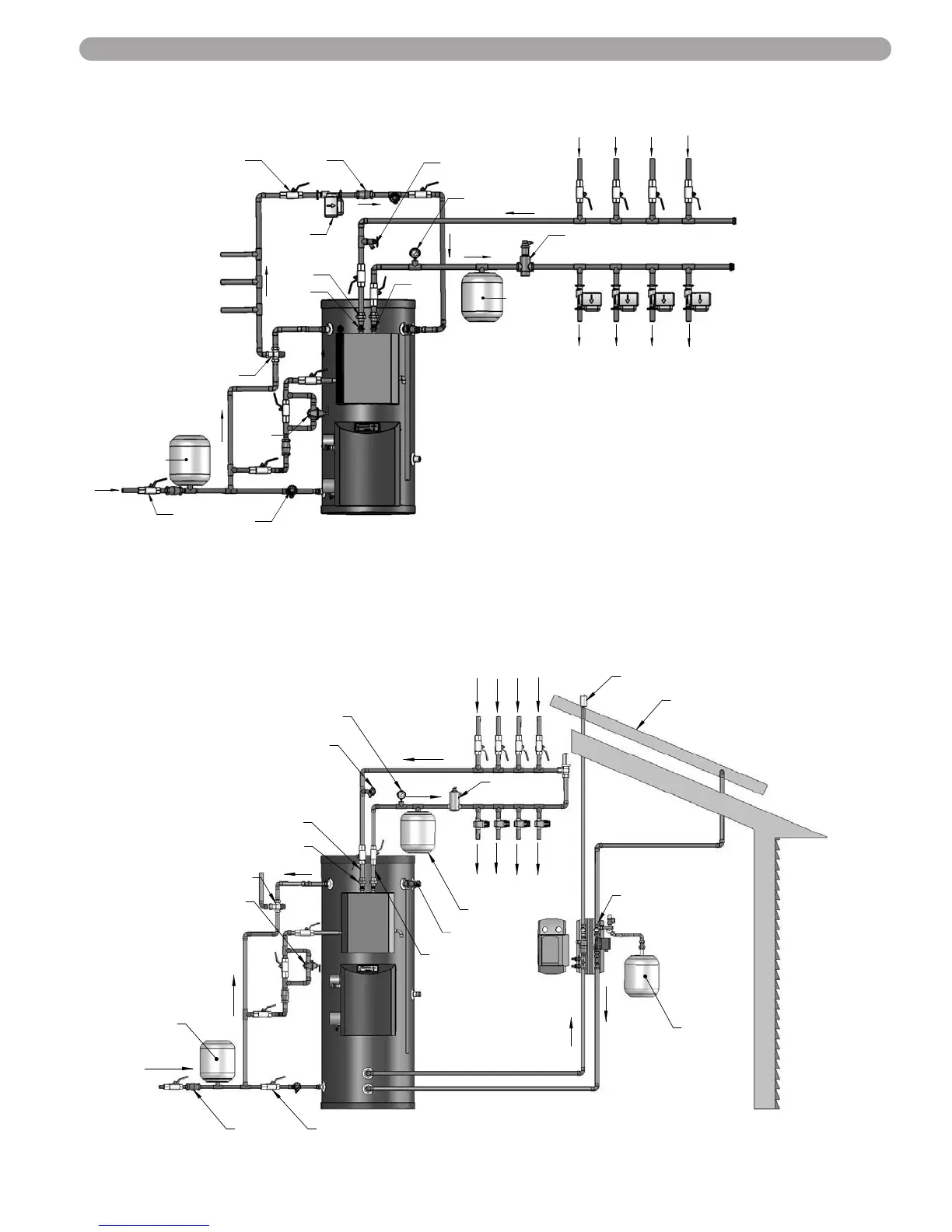
EasyManua.ls Logo

Heat Transfer Phoenix Evolution - Page 23

Heat Transfer Phoenix Evolution
76 pages
Print Icon
To Next Page IconTo Next Page
To Previous Page IconTo Previous Page
Loading...
DRAIN /PURGE VALVE
HEATING ZONES
FROM LOW TEMPERATURE
HEATING ZONES
TO LOW TEMPERATURE
TEMP/ PRESSURE GAUGE
SOLAR COLLECTOR
VALVES
ZONE
ELIMINATOR
AIR
TANK
SUPPLY
RETURN
EXPANSION
(TYP)
UNION
VALVE
REDUCING
(SUPPLIED)
MIXING VALVE
(
TYP
)
BALL VALVEBACKFLOW
PRESSURE
PREVENTOR
TANK
EXPANSION
SOLAR AIR RELEASE VENT
TANK
EXPANSION
RELIEF VALVE
SOLAR MODULE
INLET
COLD
HYDRONIC PIPING
BALL VALVE
VALVE
SHUT OFF
HEATING ZONES
FROM LOW TEMPERATURE
UNION
CHECK
COLD
HEATING ZONES
VALVE
VALVES
VALVE
MIXING VALVE
TUB
SHOWER
SINK
EXPANSION
(TYP)
VALVE
TEMP. AND PRESSURE
TANK
DRAIN
CIRCULATOR
RETURN
INLET
(TYPICAL)
DRAIN/PURGE
EXPANSION TANK
GAUGE
BALL
(SUPPLIED)
AIR ELIMINATOR
TO LOW TEMPERATURE
PHOENIX EVOLUTION WITH RECIRCULATION PIPING
WITH IFC
PRESSURE
TEDUCING
SUPPLY
LP-314-PIPING-4
11/20/09
NOTE: These drawings are meant to show system piping only. The installer is responsible for all equipment and
detailing required by local codes.
This application may not be allowed in Massachusetts.
In Massachusetts you must install a vacuum relief valve per 248 CMR.
PHOENIX EVOLUTION WITH RECIRCULATION PIPING
PHOENIX EVOLUTION SOLAR
NOTES:
1. Minimum pipe size should match connection size on Phoenix
Evolution. If you require greater flow, upsize the pipe accordingly.
2. A Thermal Expansion tank suitable for potable water must be sized
and installed within this piping system between the check valve
and the cold water inlet of the Phoenix Evolution.
Check with the Manufacturer of the Thermal Expansion tank for
proper sizing.
3. Gas Line must be rated to the maximum input capacity of the
unit. Unit must have 10 feet of pipe after gas regulator.
4. All circulators shall have an integral flow check.
22
LP-314-PIPING-5
12/14/09

Table of Contents

Related product manuals