VENTING
PART 8: VENTING, COMBUSTION AIR & CONDENSATE REMOVAL (CONTINUED)
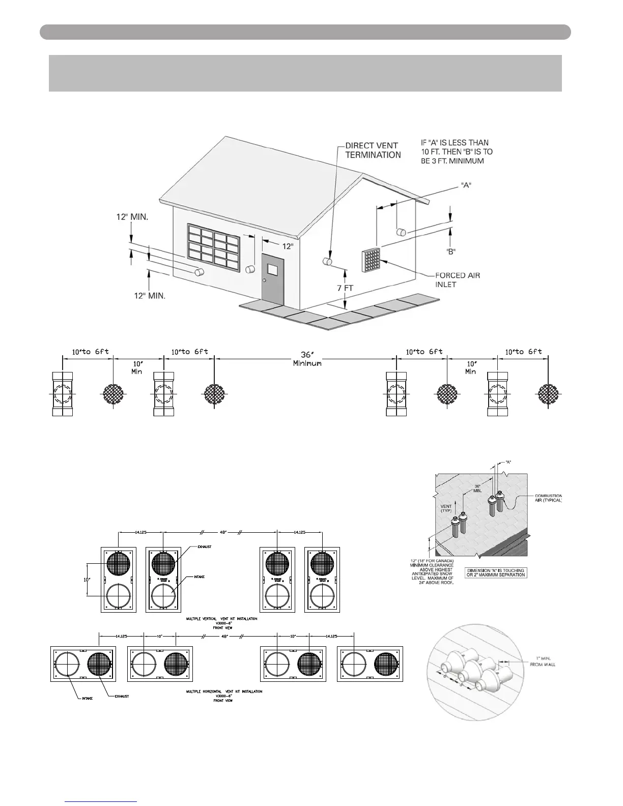
Location of exit terminals of mechanical draft and direct-vent venting systems.
(Reference: National Fuel Gas Code ANSI Z223.1/NFPA 54 2002).
Fig. 8-2 Multiple Vent Spacing*
*Note: Exhaust must extend out 1 foot. There should be no more than 2 vents and 2 intakes then a space of 36” to the
next set of vents.
*Note: There must be a minimum of 36” spacing between every 2 kit grouping.
Multiple “V” Series Vents
Fig. 8-3 Multiple Stainless Steel Horizontal Vent Kit Installation – Front View
Fig. 8-1 Multiple Vents
Fig. 8-4 Multiple Concentric Vent
Spacing – Vertical
Fig. 8-5 Multiple Concentric Vent
Spacing – Horizontal
31