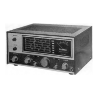
Assembly
and
Operation
of
the
Heathkit
LOW
COST
TRANSISTOR
RECEIVER
MODEL
AR-14
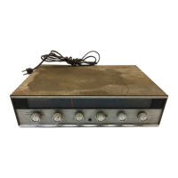
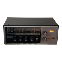
NOTE: RECEIVER
IS
SHOWN
INSTALLED IN THE
AE-55
WALNUT
CABINET
ACCESSORY.
HEATH
COMPANY
BENTON
HARBOR,
MICHIGAN
I
TABLE
OF CONTENTS
Introduction. . • . • . . . • • • . • . • . • . • . • • 2
Parts
List.
. • . . . . . . . . . • . . . . . • • . . . 3
Step-By-Step
Assembly
FM
Multiplex
Circuit
Board.
• • • • • • • • 6
Amplifier
Circuit
Board
••••••••••••
12
Preliminary
Wiring.
• • • • • • • • • • • • • • 20
Mounting
Power
Supply
Chassis,
Center
Panel,
And
Flywheel
•••••••••
22
Dial
Stringing.
• • • • • • • • • • • • • • • • • • 2 8
Chassis
Wiring.
• • • • • • • • • • • • • • • • • 29
Prewiring
Selector
Switch. • • • • • • • • • 32
Wiring
Selector
Switch
To
Circuit
Board.
• • • • • • • • • • • • • • • • • 34
Installing
Transistors.
• • • • • • • • • • • 36
Final
Wiring.
• • • • • • • • • • • • • • • • • • 38
Front
Panel,
Knob, And
Dial
Pointer
Installation.
• • • • • • • • • • • • • 42
Initial
Test
And
Adjustment.
• • • • • • • • • • 44
Final
Assembly.
• • • • • • • • • • • • • • • • • 49
Installation.
• • • • • • • • • • • • • • • • • • • • • 50
Operation.
• . • . • • • • • • • • • . • . • . . • • 53
In
Case
Of
Difficulty
•••••••••••••••
55
Troubleshooting
Chart.
• • • • • • • • • • • • • 56
Alignment
With
Instruments
••••••••••
59
Specifications.
• • • • • • • • • • • • • • • • • • 63
Circuit
Description
•••••••••••••••
67
Circuit
Board
X-Ray
Views
•••••••••
76
Chassis
Photographs.
• • • • • • • • • • • • • • • 7 8
Schematic
••
(fold-out
from
page)
••••••••
79
Copyright
C 1965
Heath Company
Heathkit
reserved
1/ 14/
66
E